Multi-Sensor (V4L2 Sensor)

Important

All the bash commands shown here are based on Genio 510/700-EVK. For Genio 510-EVK, users can follow the same step to do the whole setup by changing the naming term from 700 to 510.

Note

All command operations presented in this chapter are based on the IoT Yocto v24.0, Genio 700-EVK. You might get different operation results depending on the platform you use.

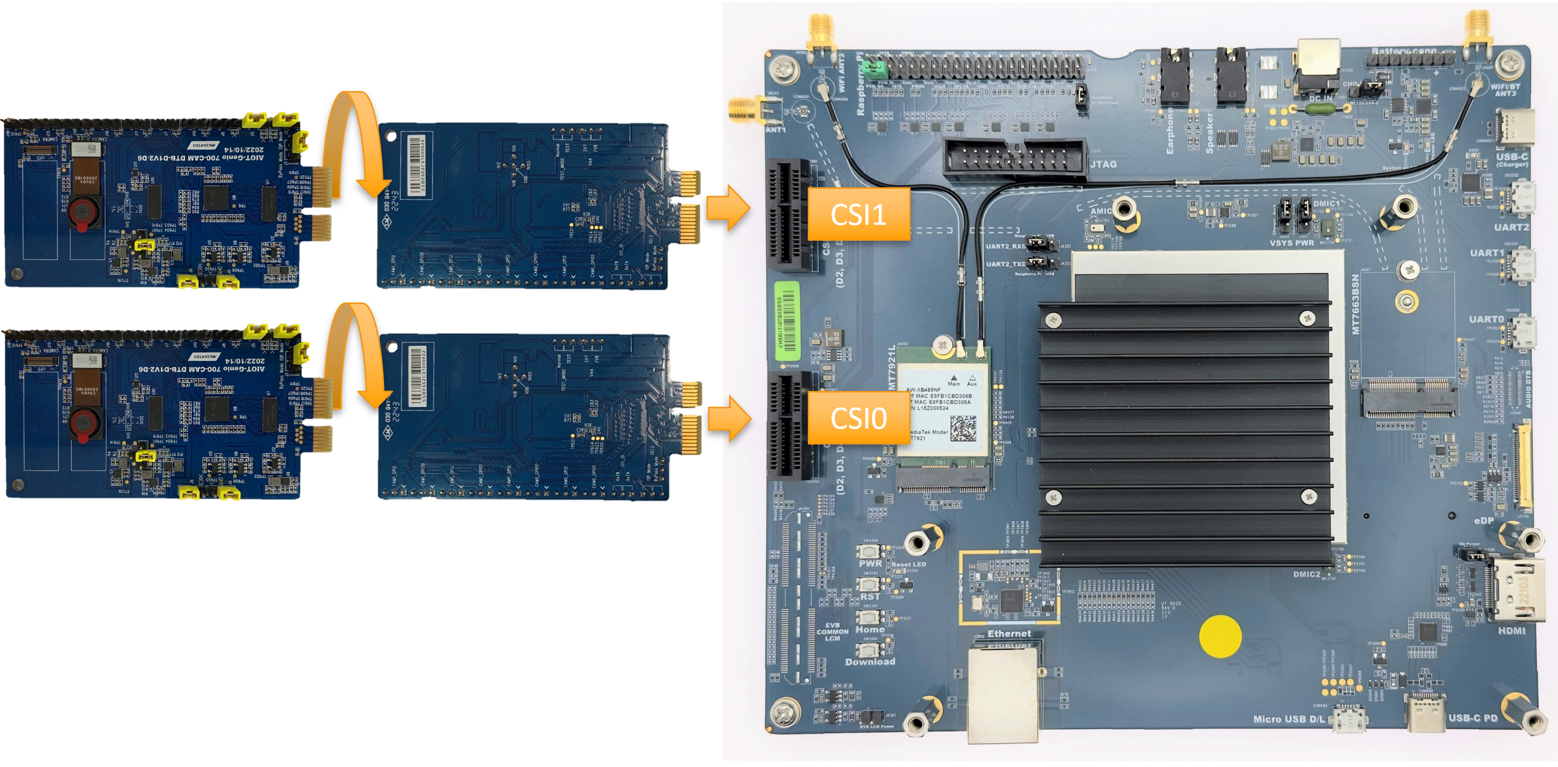
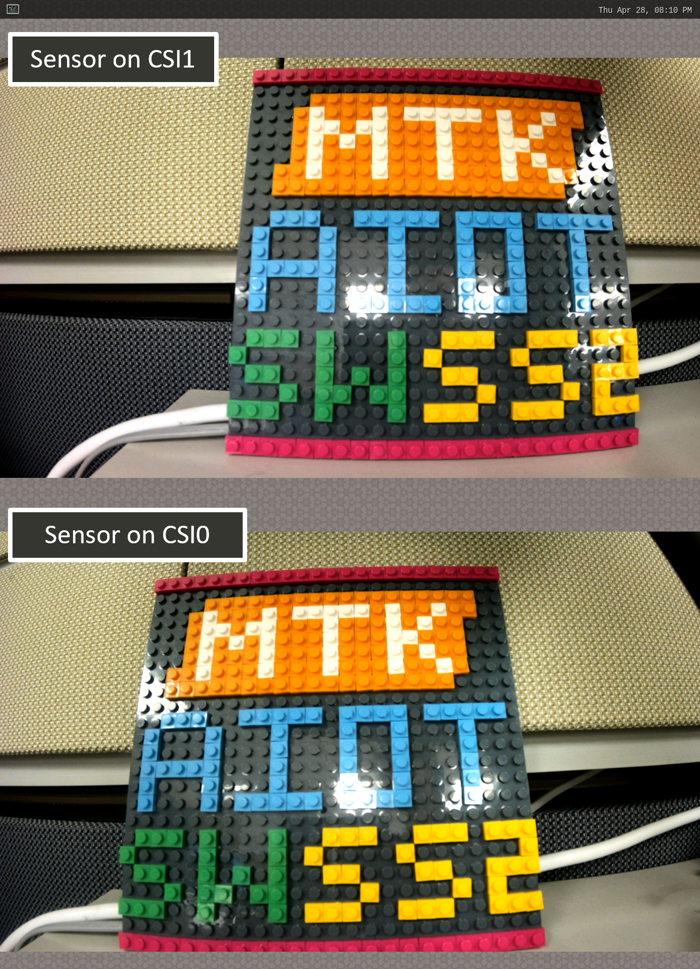
This chapter shows how to operate multi sensors under V4L2 Sensor architecture on Genio 510/700-EVK.

Select Camera Device Tree Blob Overlay

The camera device is inactive by default, so the kernel has to load a specific device tree blob overlay to enable it. Please refer to bl33u-boot for how to load DTBO.

The following table shows the supported multi-sensor combinations in V4L2 sensor architecture. IT6510FN and LT6911UXE are the proof-of-concept components. Please refer to Proof-of-Concept for the usage.

Multi Camera DTBO for Genio 510/700-EVK

Platform

CSI0

CSI1

DTBO

Usage

Genio 510/700-EVK

AP1302+ AR0830

AP1302+ AR0830

camera-ar0830-ap1302-dual-std.dtbo

Enable 4-lane CAM-DTB-D6 w/ Onsemi AR0830 on CSI0 and CSI1

Genio 510/700-EVK

AP1302+ AR0830

IT6510FN

camera-ar0830-ap1302-csi0-it6510-csi1-std.dtbo

Enable 4-lane CAM-DTB-D6 w/ Onsemi AR0830 on CSI0, and 4-lane CAM-DTB-DP to MIPI on CSI1

Genio 510/700-EVK

IT6510FN

IT6510FN

camera-it6510-dual-std.dtbo

Enable 4-lane CAM-DTB-DP to MIPI on CSI0 and CSI1

Genio 510/700-EVK

LT6911UXE

LT6911UXE

camera-lt6911uxe-dual-std.dtbo

Enable 4-lane CAM-DTB-HDMI to MIPI on CSI0 and CSI1

genio-flash --list-dtbo
List of available DTBO:
        - camera-ar0830-ap1302-dual-std.dtbo
        - camera-ar0830-ap1302-csi0-it6510-csi1-std.dtbo
        - camera-it6510-dual-std.dtbo
        - camera-lt6911uxe-dual-std.dtbo
        - ...
genio-flash --load-dtbo camera-ar0830-ap1302-dual-std.dtbo --load-dtbo gpu-mali.dtbo --load-dtbo apusys.dtbo --load-dtbo video.dtbo

Dual Onsemi AP1302 & AR0830

Hardware Setup

  1. Prepare 2x CAM-DTB-D6 and 2x Onsemi AR0830 sensors

  2. Connect the DTBs to CSI0 and CSI1 slots

    ../../../../_images/sw_yocto_app-dev_camera_g700_connect-dual-d6.png

    Genio 510/700-EVK with two CAM-DTB-D6 and Onsemi AR0830 sensor

Software Setup

  1. Select the dtbo camera-ar0830-ap1302-dual-std.dtbo through genio-flash

    genio-flash --load-dtbo camera-ar0830-ap1302-dual-std.dtbo --load-dtbo gpu-mali.dtbo --load-dtbo video.dtbo
    
  2. Find the media device of the camera system

    export MEDIA_DEV=$(v4l2-ctl -z platform:$(basename `find /sys/bus/platform/devices/ -name "*camisp"`) --list-devices | grep media)
    echo ${MEDIA_DEV}
    /dev/media3
    

    Warning

    The assigned node number for the media device may vary depending on the sequence of the probing process during the boot-up phase. As such, it is crucial to ensure the accuracy of the media device node before using the camera.

  3. Set the media topology and the format on the EVK

    ../../../../_images/sw_yocto_app-dev_camera_g700_media-topology_dual-ap1302.svg

    Media Topology Graph of Dual Onsemi AP1302 ISP and SoC

    # Set Genio 700 and Onsemi AP1302 on CSI0
    
    media-ctl -d ${MEDIA_DEV} -l "'seninf-0':1 -> 'mtk-cam camsv-0':0 [5]"                     # Enable the link between seninf-0 pad 1 and mtk-cam camsv-0 pad 0
    media-ctl -d ${MEDIA_DEV} -l "'ap1302.5-003c':2 -> 'seninf-0':0 [1]"                       # Enable the link between ap1302.5-003c pad 2 and seninf-0 pad 0
    
    media-ctl -d ${MEDIA_DEV} -V "'ap1302.5-003c':2 [fmt:UYVY8_1X16/1920x1080 field:none]"     # Set UYVY/1920x1080 to ap1302.5-003c pad 2
    media-ctl -d ${MEDIA_DEV} -V "'seninf-0':1 [fmt:UYVY8_1X16/1920x1080 field:none]"          # Set UYVY/1920x1080 to seninf-0 pad 1
    media-ctl -d ${MEDIA_DEV} -V "'mtk-cam camsv-0':1 [fmt:UYVY8_1X16/1920x1080 field:none]"   # Set UYVY/1920x1080 to mtk-cam camsv-0 pad 1
    
    # Set Genio 700 and Onsemi AP1302 on CSI1
    
    media-ctl -d ${MEDIA_DEV} -l "'seninf-1':1 -> 'mtk-cam camsv-1':0 [5]"                     # Enable the link between seninf-1 pad 1 and mtk-cam camsv-1 pad 0
    media-ctl -d ${MEDIA_DEV} -l "'ap1302.2-003c':2 -> 'seninf-1':0 [1]"                       # Enable the link between ap1302.2-003c pad 2 and seninf-1 pad 0
    
    media-ctl -d ${MEDIA_DEV} -V "'ap1302.2-003c':2 [fmt:UYVY8_1X16/1920x1080 field:none]"     # Set UYVY/1920x1080 to ap1302.2-003c pad 2
    media-ctl -d ${MEDIA_DEV} -V "'seninf-1':1 [fmt:UYVY8_1X16/1920x1080 field:none]"          # Set UYVY/1920x1080 to seninf-1 pad 1
    media-ctl -d ${MEDIA_DEV} -V "'mtk-cam camsv-1':1 [fmt:UYVY8_1X16/1920x1080 field:none]"   # Set UYVY/1920x1080 to mtk-cam camsv-1 pad 1
    
  4. Find the video device of the camera system

    declare -a VIDEO_DEV=(`for i in {0..7}; do media-ctl -d ${MEDIA_DEV} --entity "mtk-cam camsv-$i main-stream"; done | tr "\n" " "`)
    
  5. Launch Dual Onsemi AP1302 pipeline to show dual Onsemi AP1302 images on the Weston desktop

    gst-launch-1.0 -v v4l2src device=${VIDEO_DEV[0]} io-mode=dmabuf-import ! video/x-raw,width=1920,height=1080,format=UYVY ! v4l2convert output-io-mode=dmabuf ! video/x-raw,width=1280,height=720 ! waylandsink sync=false &
    gst-launch-1.0 -v v4l2src device=${VIDEO_DEV[1]} io-mode=dmabuf-import ! video/x-raw,width=1920,height=1080,format=UYVY ! v4l2convert output-io-mode=dmabuf ! video/x-raw,width=1280,height=720 ! waylandsink sync=false &
    

After the above steps, the video data from two Onsemi AP1302 will be shown on the Weston desktop.

../../../../_images/sw_yocto_app-dev_camera_g700_dual-ap1302-shown-on-weston.png

Dual Onsemi AP1302 ISP and AR0830 sensor shown on the Weston desktop