Connecting Board to Host
With IoT Yocto, there are several options to connect your host PC to the Genio boards for debugging and development purposes:
UART Port: The UART port provides access to Boot ROM, bootloader and kernel console access in IoT Yocto. This design is shared across all Genio EVKs.
- USB: Various functionality is provided via the USB of Genio SoCs in it’s default configuration:
Image Download: You can program the on-board storage (EMMC or UFS) through USB with Genio Tools.
- Ethernet connectivity: The device is configured to expose a virtual Ethernet connection with the host via multiple protocols.
This allows various networking services to be exposed such as ssh / scp to obtain shell & file transfer functionality.
Debugging capabilites: The device is also configured as an Android Debug Bridge (ADB) device.
Note
If using Windows, installation of the Google Android USB driver and FTDI VCP USB driver is required, to Boot as outlined in the Fastboot and ADB and UART Setup sections of Setup Tool Environment respectively.
Open Device Manager and confirm that the Google Android USB driver appears under Android Device \\ Android Bootloader Interface and the FTDI VCP USB driver appears under Ports (COM & LPT) \\ USB Serial Port (COMx) (where x is the port assigned by your system).
Further details regarding both USB drivers can be found in the flash trouble-shooting section.
Connect a USB cable between the host PC and the UART0 connector labeled
UART0.Connect a second USB cable between the host PC and the USB0 connector labeled
USB0.Connect the supplied 12V power adapter into the 12V DC socket labeled
DC IN.[Optional] Connect an ethernet cable between a suitable network point and the RJ-45 Ethernet port labeled
Ethernet.
The location of the UART0, USB0 and Ethernet ports on Genio 350-EVK are shown below:
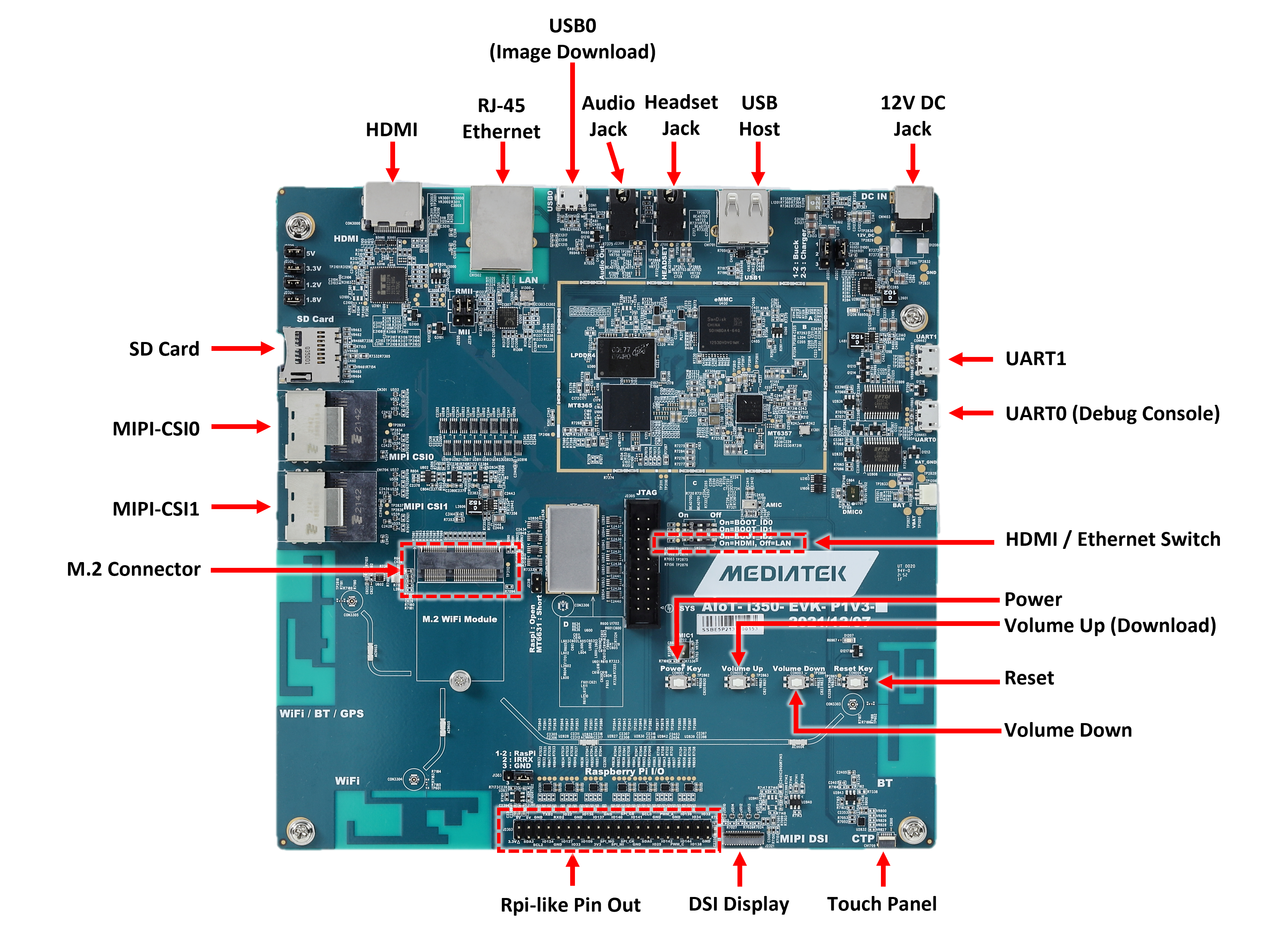
Ports of Genio 350-EVK main board
Connect the supplied 12V power adapter into the 12V DC socket labeled
DC IN. Once connected to power source, the Power LED and System on LED should light up, as shown below: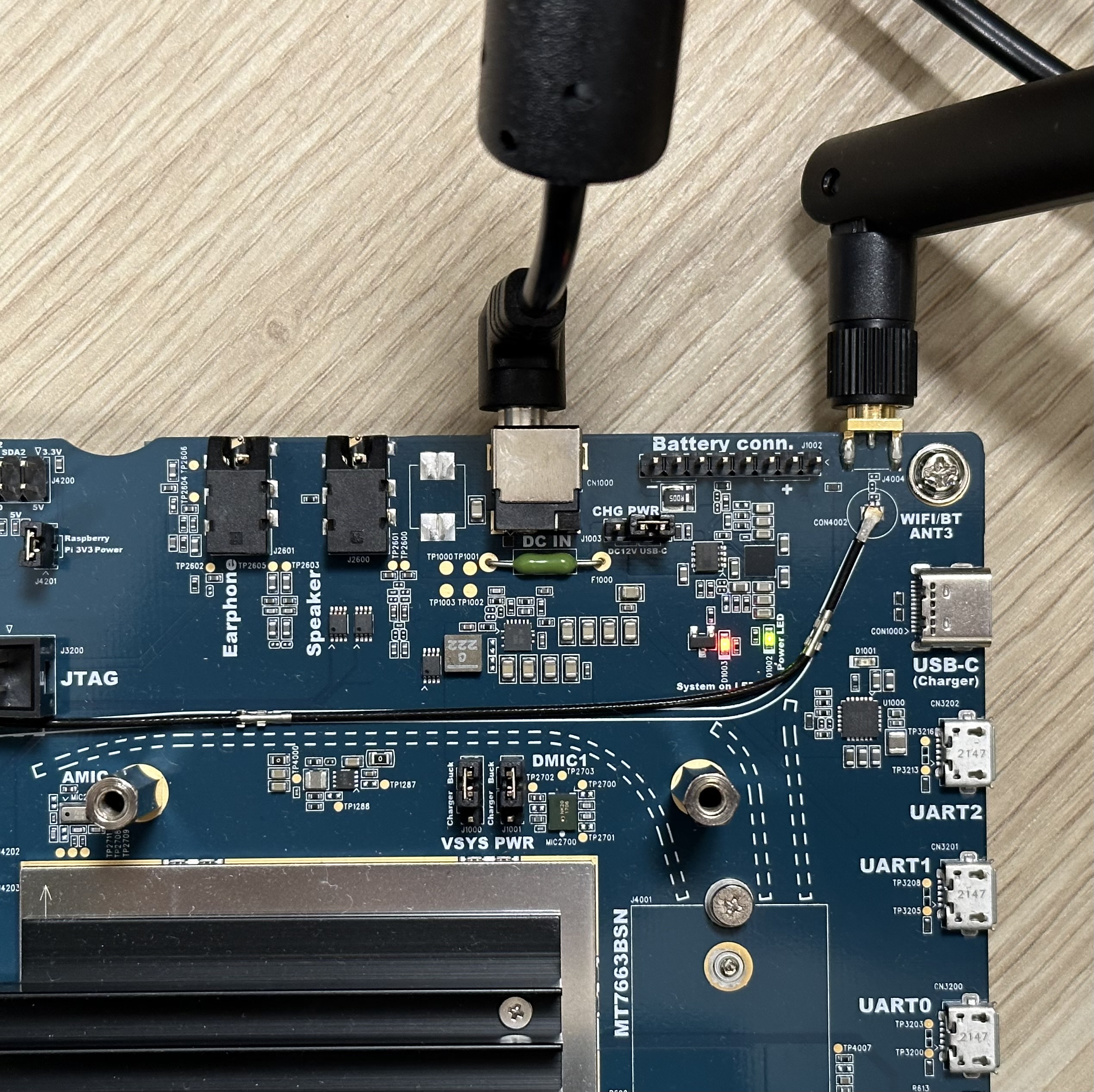
Connecting to 12V DC power
Connect a micro USB cable between the host PC and the UART0 connector labeled
UART0.Connect a second micro USB cable between the host PC and the USB0 connector labeled
Micro USB D/L.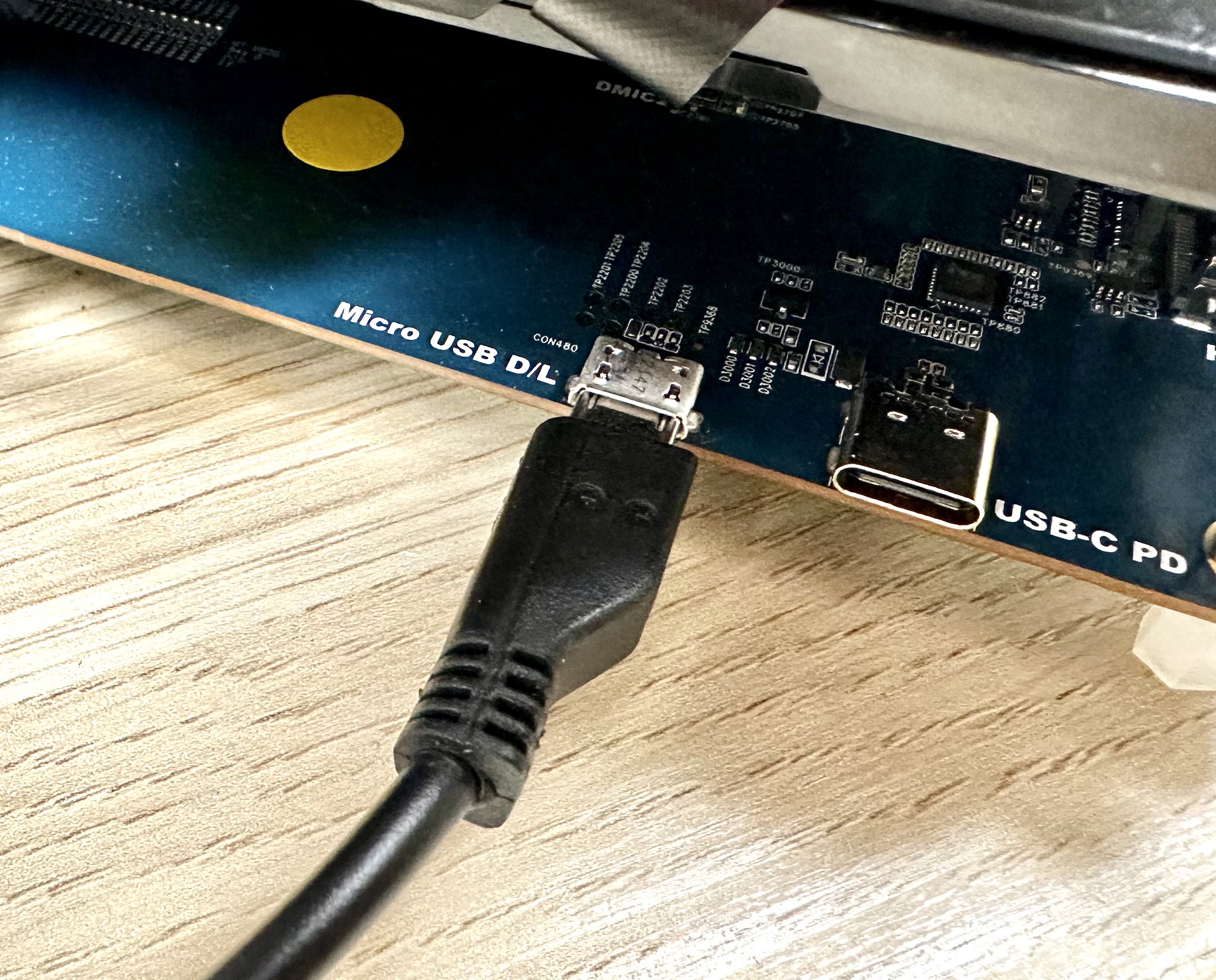
Connecting to Micro USB D/L port
Note
The EVK board will power on when the Micro USB D/L port is connected, regardless of the state of the auto power on jumper pin J3001.
[Optional] Connect an ethernet cable between a suitable network point and the RJ-45 Ethernet port labeled
Ethernet.
The location of the UART0, Micro USB D/L and Ethernet ports on Genio 350-EVK are shown below:
Note
The
USB-C PDconnector on the EVK maps to USB1 of MT8370/MT8390. It is configured as an USB host-only port and does not expose RNDIS nor ADB devices.The
USB-C (Charger)connector, next to theUART2connector, is for charging purposes only and is not supported by IoT Yocto.
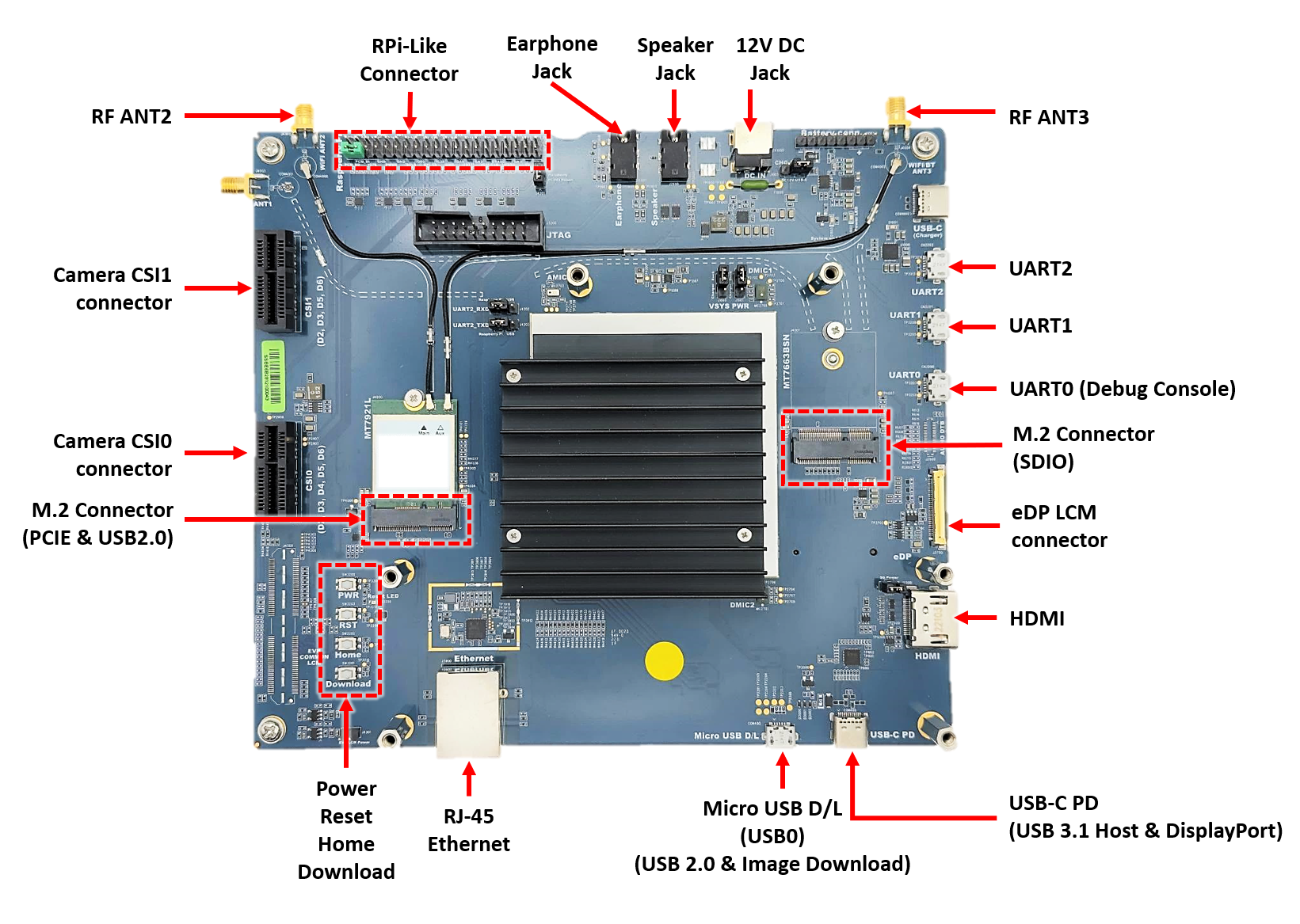
Ports of Genio 510/700-EVK main board
Connect the supplied 12V power adapter into the 12V DC socket labeled
DC IN. Once connected to power source, the Power LED and System on LED should light up, as shown below:
Connecting to 12V DC power
Connect a micro USB cable between the host PC and the UART0 connector labeled
UART0.Connect a second micro USB cable between the host PC and the USB0 connector labeled
Micro USB D/L.
Connecting to Micro USB D/L port
Note
The EVK board will power on when the Micro USB D/L port is connected, regardless of the state of the auto power on jumper pin J3001.
[Optional] Connect an ethernet cable between a suitable network point and the RJ-45 Ethernet port labeled
Ethernet.
The location of the UART0, Micro USB D/L and Ethernet ports on Genio 350-EVK are shown below:
Note
The
USB-C PDconnector on the EVK maps to USB1 of MT8370/MT8390. It is configured as an USB host-only port and does not expose RNDIS nor ADB devices.The
USB-C (Charger)connector, next to theUART2connector, is for charging purposes only and is not supported by IoT Yocto.
Ports of Genio 510/700-EVK main board
Connect the supplied 12V power adapter into the 12V DC socket labeled
DC JACK IN. Once connected to power source, the LED_DC and LED_PWR LEDs should light up, as shown below: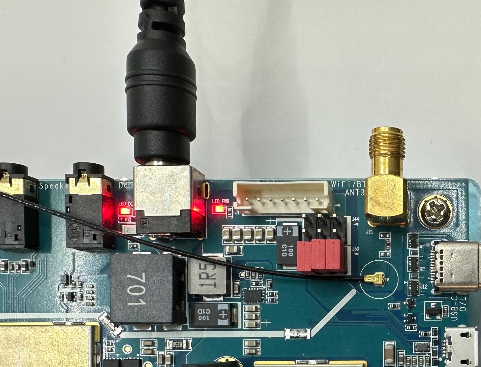
Connecting to 12V DC power
Connect a Micro USB cable between the host PC and the UART0 connector labeled
UART0.Connect a Type-C USB cable between the host PC and the USB0 connector labeled
USB-C D/L.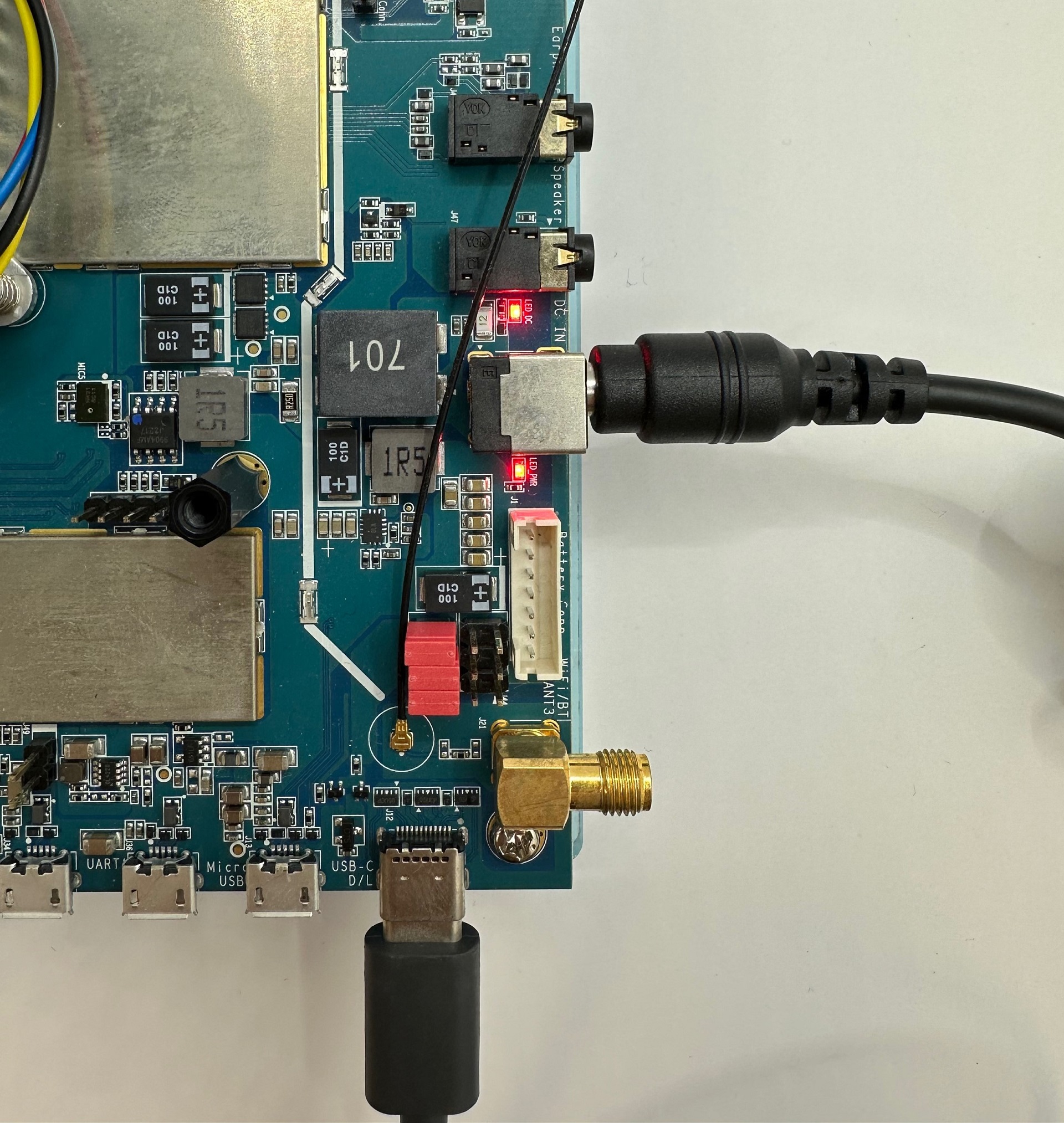
Connecting to Type-C D/L port
Note
The EVK board will power on when the Type-C USB D/L port is connected, regardless of the state of the auto power on jumper pin J51.
[Optional] Connect an ethernet cable between a suitable network point and the RJ-45 Ethernet port labeled
Ethernet.
The location of the UART0, USB-C D/L and Ethernet ports on Genio 1200-EVK are shown below:
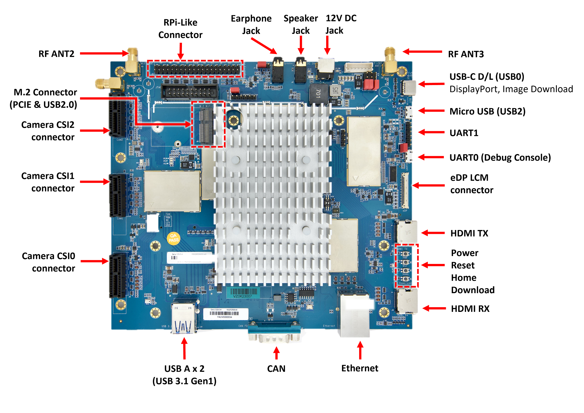
Ports of Genio 1200-EVK main board
Genio 520/720-EVK can be powered by either the
DC INport, or the USB-CPD Powerport. IoT Yocto BSP does not support battery as power source.Before connecting power source, select the power source you need by setting the
Power Pathjumper first: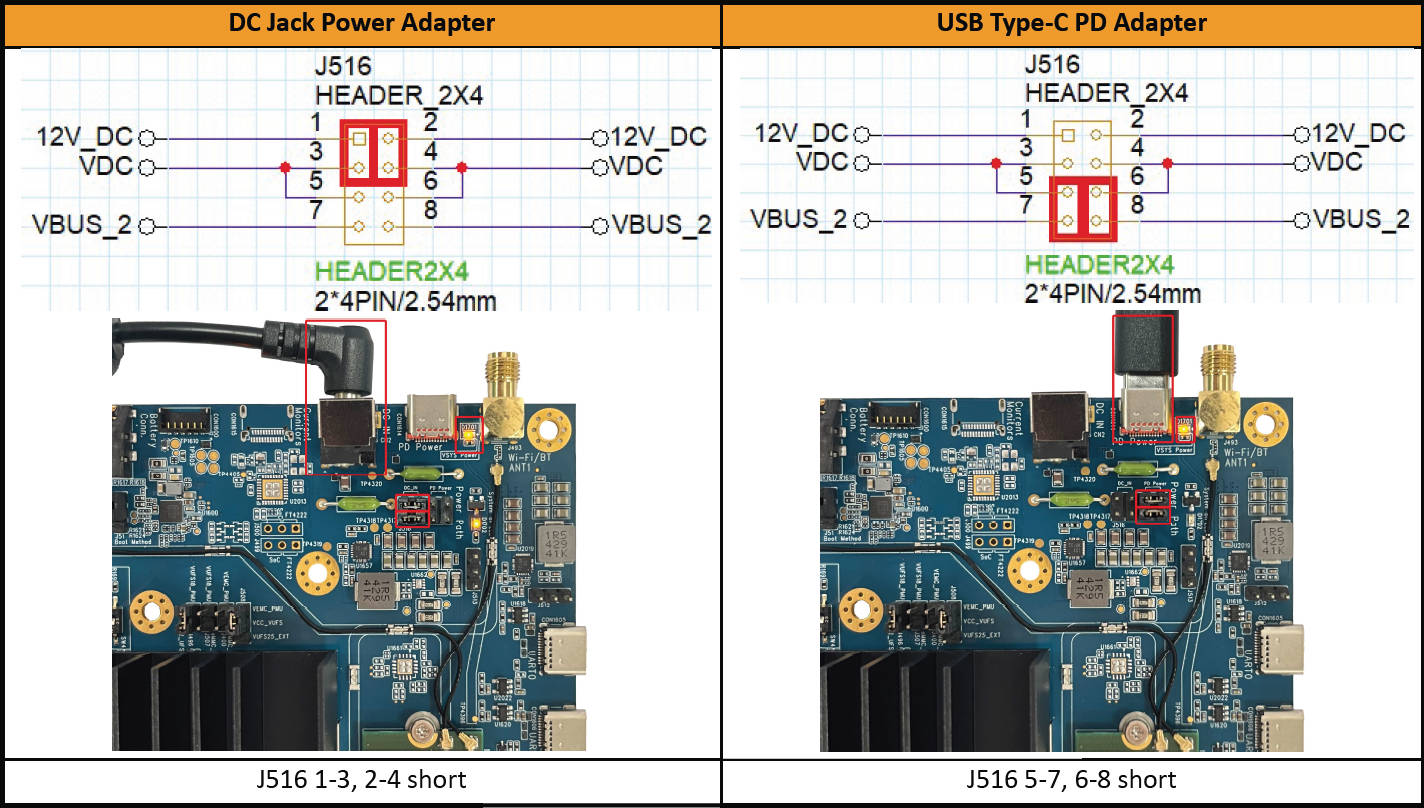
Select 12V DC or USB-C PD power input
Then, connect the 12V power adapter or a USB-C PD adaptor according to your configuration.
Connect a USB-C cable between the host PC and the UART0 Type-C connector labeled
UART0.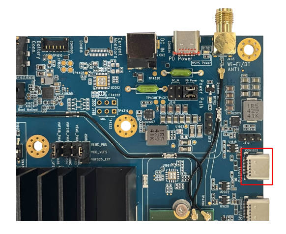
Connecting to USB Type-C UART0 port
Connect a second USB-C cable between the host PC and the Type-C connector labeled
USB 3.2 P0 Download.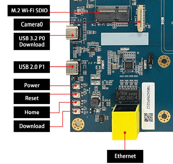
Connecting to USB 3.2 P0 Download port
Note
The EVK board will power on when the Micro USB D/L port is connected, regardless of the state of the auto power on jumper pin J51.
Genio 520/720-EVK can be configured to accept USB download payload from USB P0 or P1. Since we are going to use USB P0 to download payload from host to the board, make sure
Boot Selectis configured as:SW5 1: OFFSW5 2: ON
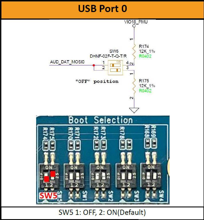
Configure USB0 as download port
While this is the default out-of-box config, please confirm that it’s set to download from USB P0 before proceeding to next steps.