There are 4 DMIC interfaces available on the Genio 510/700/1200, where each interface supports 2 channels, you can indeed receive data from up to 8 channels simultaneously.
To remove DC offset generated by external DMIC components, enable infinite impulse response mode.
IIR mode is enabled in DMIC by default. If not needed, remove it from the device tree.
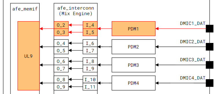
By default, the PDM interface activates DMIC clock signals in a particular sequence based on the number of channels being used.
For 2 channels, only DMIC1_CLK is enabled.
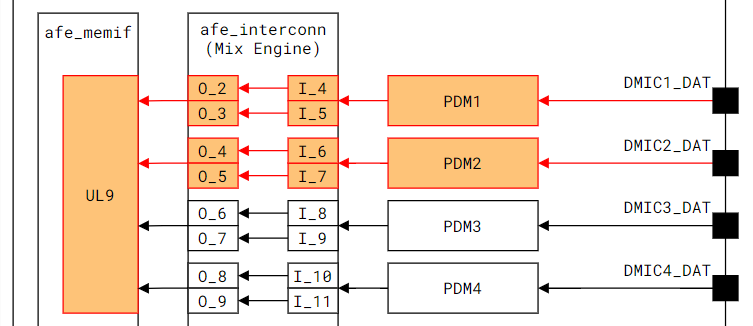
For 4 channels, both DMIC1_CLK and DMIC2_CLK are enabled.
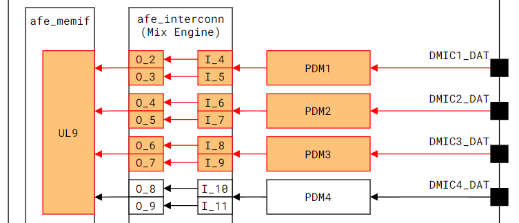
For 6 channels, DMIC1_CLK, DMIC2_CLK, and DMIC3_CLK are enabled.
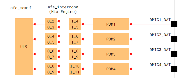
For 8 channels, all four clock signals from DMIC1_CLK to DMIC4_CLK are enabled.
However, if the hardware wiring of the DMICs doesn’t follow this default order, users have the flexibility to specify a custom clock enable sequence through the device tree. A property can be added within the device tree to outline the preferred order.
The clock indices that are allowed range from 0 to 3, corresponding to DMIC1 through DMIC4.
E.g.
The sample DTS setting below shows the reordering enable sequence as DMIC1 -> DMIC4 -> DMIC3 -> DMIC2
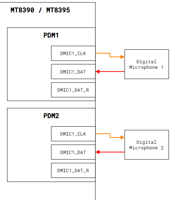
In clk-mono mode, each DMIC component is associated with an individual clock signal. This indicates
that each of the two DMIC components is connected to the different interface.
To support clk-mono mode, additional configurations must be made within the Device Tree Source file to accurately represent the hardware design and ensure the correct pathways for clock signals are established.
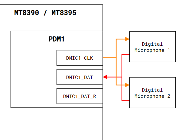
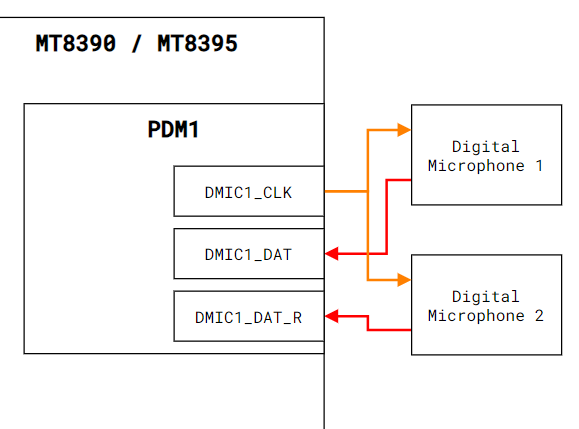
MT8390/MT8395 typically uses a PDM interface in one-wire mode by default, which means that a single data pin is shared between two digital microphones. In this configuration, one PDM data line is used for both the left and right microphone channels.
However, if you are implementing a two-wire mode, where each DMIC has its own dedicated data pin (thus providing separate PDM data lines for each microphone), an additional property needs to be specified in the Device Tree Source file to configure the hardware for this mode.
The DMIC clock phase setting configures the phase for hardware to latch data. Different phase
settings are used to prevent latching data at transition area. In general, using the default
phase setting is enough, there is no need to set this property.
For the MT8390/MT8395 DMIC interface, there are 8 selectable phases per data pin. You can configure
these phase settings using this property in the DMIC node in the DTS file.
For one-wire mode, the default phase settings is <0 4>. This indicates that one microphone will latch data at phase 0, and the other at phase 4. Because two DMICs share one data pin, so each DMIC has only 4 phases to set.
mediatek,dmic-clk-phases=<0~34~7>;
For two-wire mode, the default phase settings is <0 0>. This means that each microphone will latch data at phase 0. In two-wire mode, each DMIC has 8 phases to set.
mediatek,dmic-clk-phases=<0~70~7>;
Here is an example of how to specify it for a two-wire mode configuration. In this case, DMIC0 will
latch data at phase 0, and DMIC1 will latch data at phase 7.
The following table explains the variables used in DMIC gain control. All gain settings are
adjusted based on a reference value, which is 0x80000 representing 0 dB.