YUV Sensor (V4L2 Sensor)
Important
All the bash commands shown here are based on Genio 510/700-EVK. For Genio 510-EVK, users can follow the same step to do the whole setup by changing the naming term from 700 to 510.
Note
All command operations presented in this chapter are based on Genio 700-EVK and Onsemi AP1302 ISP and AR0830 sensor. You might get different operation results depending on the platform you use.
This chapter shows how to receive YUV sensor data and directly dump it to the DRAM under V4L2 Sensor architecture on Genio 510/700-EVK. There are 8x camera DMA engines in Genio 510/700.
Camera Daughter Board
The YUV camera DTB for Genio 510/700-EVK is CAM DTB-D6.
It contains Onsemi AP1302 ISP and AR0830 Sensor.
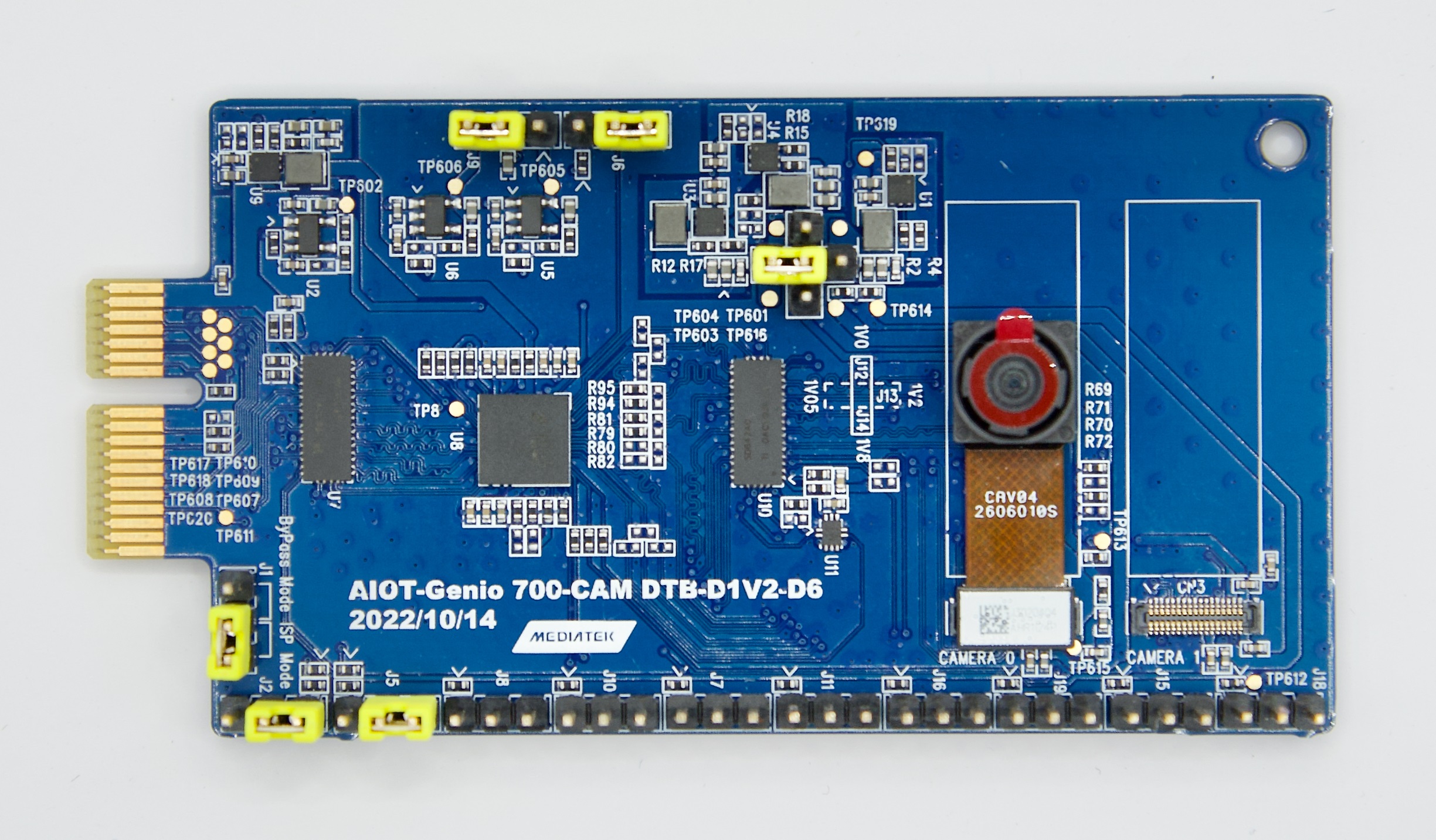
Camera DTB D6 - Onsemi AP1302 ISP and AR0830 Sensor
Connect The Camera To The EVK
There are 2 MIPI-CSI sockets on Genio 510/700-EVK, which are CSI0, and CSI1.
In the following figure, the camera DTB is connected to the CSI0 socket.
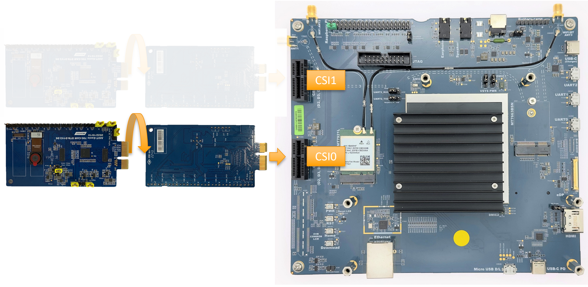
Connect Camera DTB D6 to Genio 510/700-EVK
The hardware connection is AR0830 ---> AP1302 ---> MIPI-CSI On EVK.
The camera daughter board can be configured in ISP mode and Bypass mode.
In ISP mode, the images from the AR0830 camera module are passed to AP1302 ISP before being received by the EVK.
In Bypass mode, the images from the AR0830 camera module are transferred to the EVK directly.
By default, IoT Yocto only supports ISP mode.
To configure the camera DTB D6 to ISP mode, you MUST set 6 jumpers and 1 camera sensor as shown in the figure below. The jumpers MUST be correctly set and the camera sensor MUST be connected to the CAMERA 0 slot.
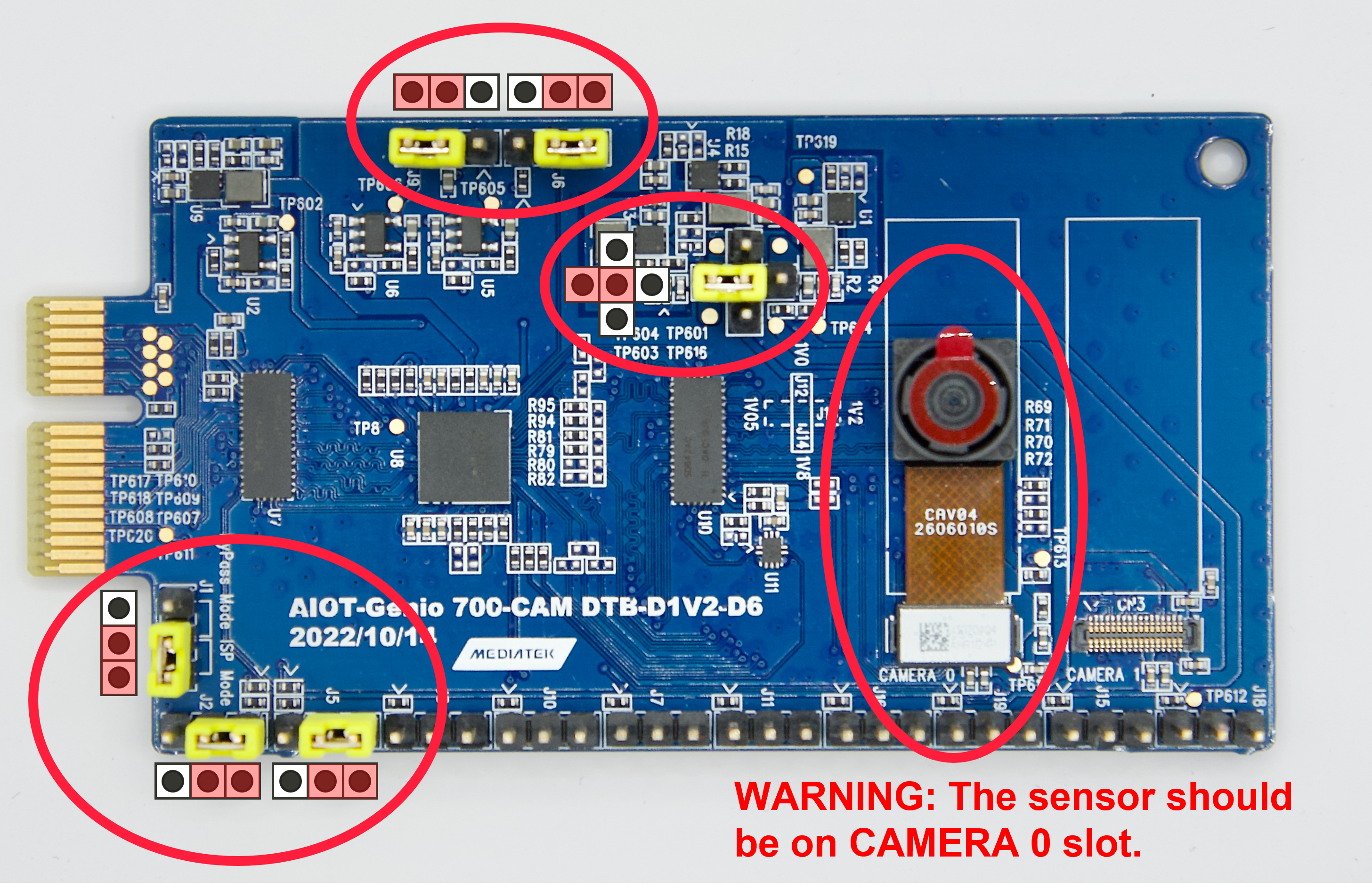
Camera DTB D6 - ISP mode
Warning
Please make sure all the above settings, including the jumpers, camera slot, and MIPI-CSI socket, are correct. Otherwise, the I2C connection between the sensor, ISP, and SoC will fail.
Select Camera Device Tree Blob Overlay
The camera device is inactive by default, so the kernel has to load a specific device tree blob overlay to enable it. Please refer to the bl33 (u-boot) section for more details.
The following table shows the supported multi-sensor combinations in V4L2 sensor architecture. IT6510FN and LT6911UXE are the proof-of-concept components. Please refer to Proof-of-Concept for the usage.
Platform |
CSI0 |
CSI1 |
DTBO |
Usage |
|---|---|---|---|---|
Genio 510/700-EVK |
AP1302+ AR0830 |
x |
camera-ar0830-ap1302-csi0-std.dtbo |
Enable 4-lane CAM-DTB-D6 w/ Onsemi AR0830 on CSI0 |
Genio 510/700-EVK |
IT6510FN |
x |
camera-it6510-csi0-std.dtbo |
Enable 4-lane CAM-DTB-DP to MIPI on CSI0 |
Genio 510/700-EVK |
LT6911UXE |
x |
camera-lt6911uxe-csi0-std.dtbo |
Enable 4-lane CAM-DTB-HDMI to MIPI on CSI0 |
genio-flash --list-dtbo
List of available DTBO:
- camera-ar0830-ap1302-csi0-std.dtbo
- camera-it6510-csi0-std.dtbo
- camera-lt6911uxe-csi0-std.dtbo
- ...
genio-flash --load-dtbo camera-ar0830-ap1302-csi0-std.dtbo --load-dtbo gpu-mali.dtbo --load-dtbo apusys.dtbo --load-dtbo video.dtbo
Supported Formats And Sizes
The array of supported formats and sizes depends on the two primary aspects:
The capabilities of the sensor and the corresponding driver implementation.
The capabilities of the SoC (System on a Chip) and the corresponding driver implementation.
A couple of examples would further explain this:
An external ISP (Image Signal Processor) such as the Onsemi AP1302 can scale the size of sensor images up to a size of 13MP. It can then export these images in some formats, including YUV422, YUV420, RGB888, etc. However, the SoC can only accept the YUV422-8bit format and can process images up to 16MP in size. It is also crucial to consider other influential factors such as the throughput of the MIPI C/D-PHY data lane.
The ITE IT6510 is a bridge IC converting the input from a DP signal into MIPI CSI (Video) and I2S (Audio) signals. It can support up to an FHD@120Hz, 4K@30Hz DP signal, but the signal is also somewhat dependent on the DP signal source. The sizes reported by the IT6510 driver are from the IT6510 hardware, which also represents the size of the DP source.
The degree of flexibility for setting the format and the size is subject to the sensor design and the driver implementation. Some sensors (e.g., ITE IT6510) provide a fixed set of formats and sizes, while some (e.g., Onsemi AP1302) can scale up/down the size in a wide range. Regardless of how the sensor determines its format and size, if the SoC supports those specifications, the user can set the SoC through the standard V4L2 interface and obtain the images from the video device node.
Media Device
The media device represents the internal topology of a media system like ISP. The topology setting including links, pads, and entities can be set through the media device. Therefore, the first step is to find the target media device node.
export MEDIA_DEV=$(v4l2-ctl -z platform:$(basename `find /sys/bus/platform/devices/ -name "*camisp"`) --list-devices | grep media)
echo ${MEDIA_DEV}
/dev/media3
Warning
The assigned node number for the media device may vary depending on the sequence of the probing process during the boot-up phase. As such, it is crucial to ensure the accuracy of the media device node before using the camera.
Video Device
The video device is the interface for users to obtain the images. On Genio 510/700-EVK, they are called mtk-cam camsv-* main-stream.
The media-ctl is a useful tool to list video devices.
declare -a VIDEO_DEV=(`for i in {0..7}; do media-ctl -d ${MEDIA_DEV} --entity "mtk-cam camsv-$i main-stream"; done | tr "\n" " "`)
echo ${VIDEO_DEV[*]}
/dev/video53 /dev/video54 /dev/video55 /dev/video56 /dev/video57 /dev/video58 /dev/video59 /dev/video60
Warning
The assigned node number for the video device may vary depending on the sequence of the probing process during the boot-up phase. As such, it is crucial to ensure the accuracy of the video device node before using the camera.
Launch Camera
The initial step is to link all the necessary components within the media device. The structure of the YUV camera pipeline is quite straightforward. It fundamentally incorporates only three components: the sensor, SENINF, and CAMSV.
media-ctl -d ${MEDIA_DEV} -l "'seninf-0':1 -> 'mtk-cam camsv-0':0 [5]"
media-ctl -d ${MEDIA_DEV} -l "'ap1302.5-003c':2 -> 'seninf-0':0 [1]"
The second step is to assign the correct format and size to each component incorporated in the camera pipeline.
media-ctl -d ${MEDIA_DEV} -V "'ap1302.5-003c':2 [fmt:UYVY8_1X16/1920x1080 field:none]"
media-ctl -d ${MEDIA_DEV} -V "'seninf-0':1 [fmt:UYVY8_1X16/1920x1080 field:none]"
media-ctl -d ${MEDIA_DEV} -V "'mtk-cam camsv-0':1 [fmt:UYVY8_1X16/1920x1080 field:none]"
For the third step, it’s necessary to identify the correct video device node. For further information on this, please refer to Video Device.
declare -a VIDEO_DEV=(`for i in {0..7}; do media-ctl -d ${MEDIA_DEV} --entity "mtk-cam camsv-$i main-stream"; done | tr "\n" " "`)
echo ${VIDEO_DEV[*]}
/dev/video53 /dev/video54 /dev/video55 /dev/video56 /dev/video57 /dev/video58 /dev/video59 /dev/video60
Important
You have to select the video node that corresponds to the CAMSV instance linked in the second step.
In this given example, mtk-cam camsv-0 is the linked instance, hence the video device node should be ${VIDEO_DEV[0]} or /dev/video53.
Lastly, to activate the camera, the user can use v4l2-ctl, gst-launch-1.0, or other V4L2 applications.
Use
v4l2-ctlv4l2-ctl -d ${VIDEO_DEV[0]} --set-fmt-video=width=1920,height=1080,pixelformat=UYVY --stream-mmap --stream-count=10 --stream-to=/tmp/ap1302.yuv --verboseUse
gst-launch-1.0gst-launch-1.0 v4l2src device=${VIDEO_DEV[0]} ! video/x-raw,width=1920,height=1080,format=UYVY ! v4l2convert output-io-mode=dmabuf-import ! video/x-raw,width=1280,height=720 ! waylandsink sync=false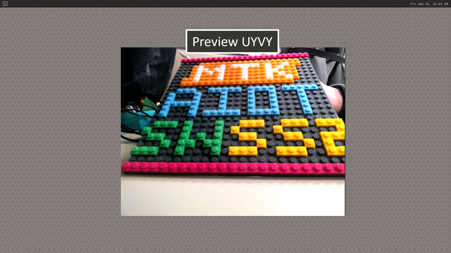
Show Preview stream on Weston
Note
To use MediaTek video codec and MDP hardware, the user has to load video.dtbo. For more details, please refer to Genio 700-EVK Video Codec.