Genio 350-EVK
This evaluation kit is available to our technology partners to evaluate the MT8365 processor for solution design and development. This section describes board features that are relevant to IoT Yocto.
Documentation
For Genio 350-EVK hardware documentation and the EVK User Guide, please visit https://genio.mediatek.com/genio-350.
|
|
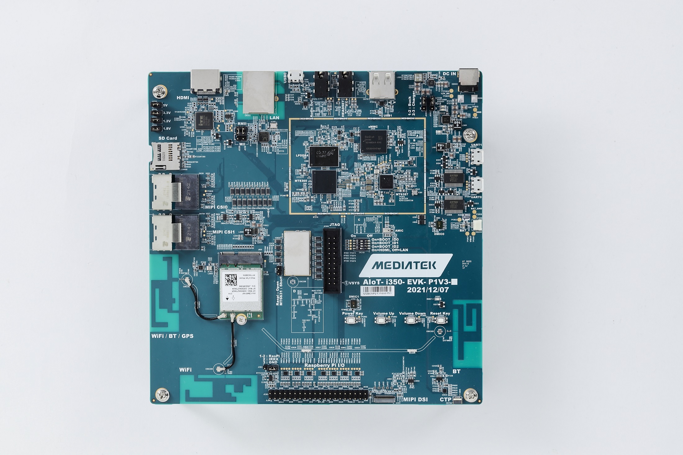
Genio 350-EVK Ports
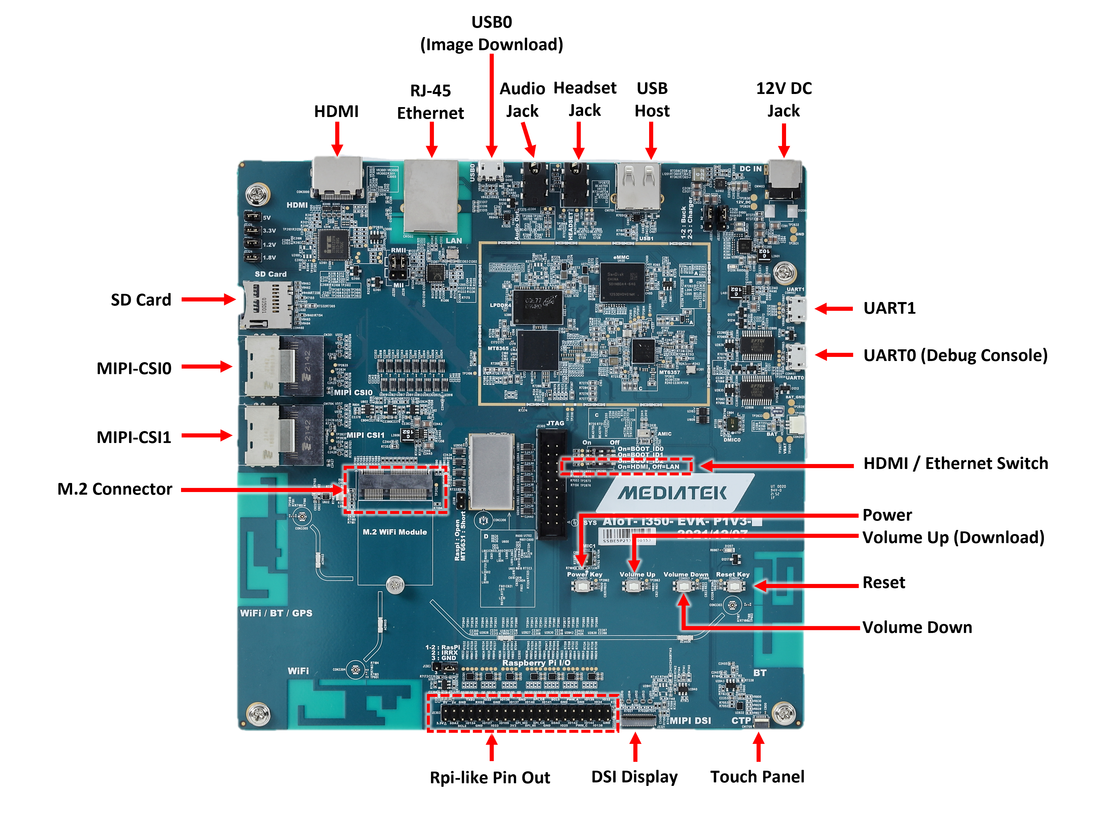
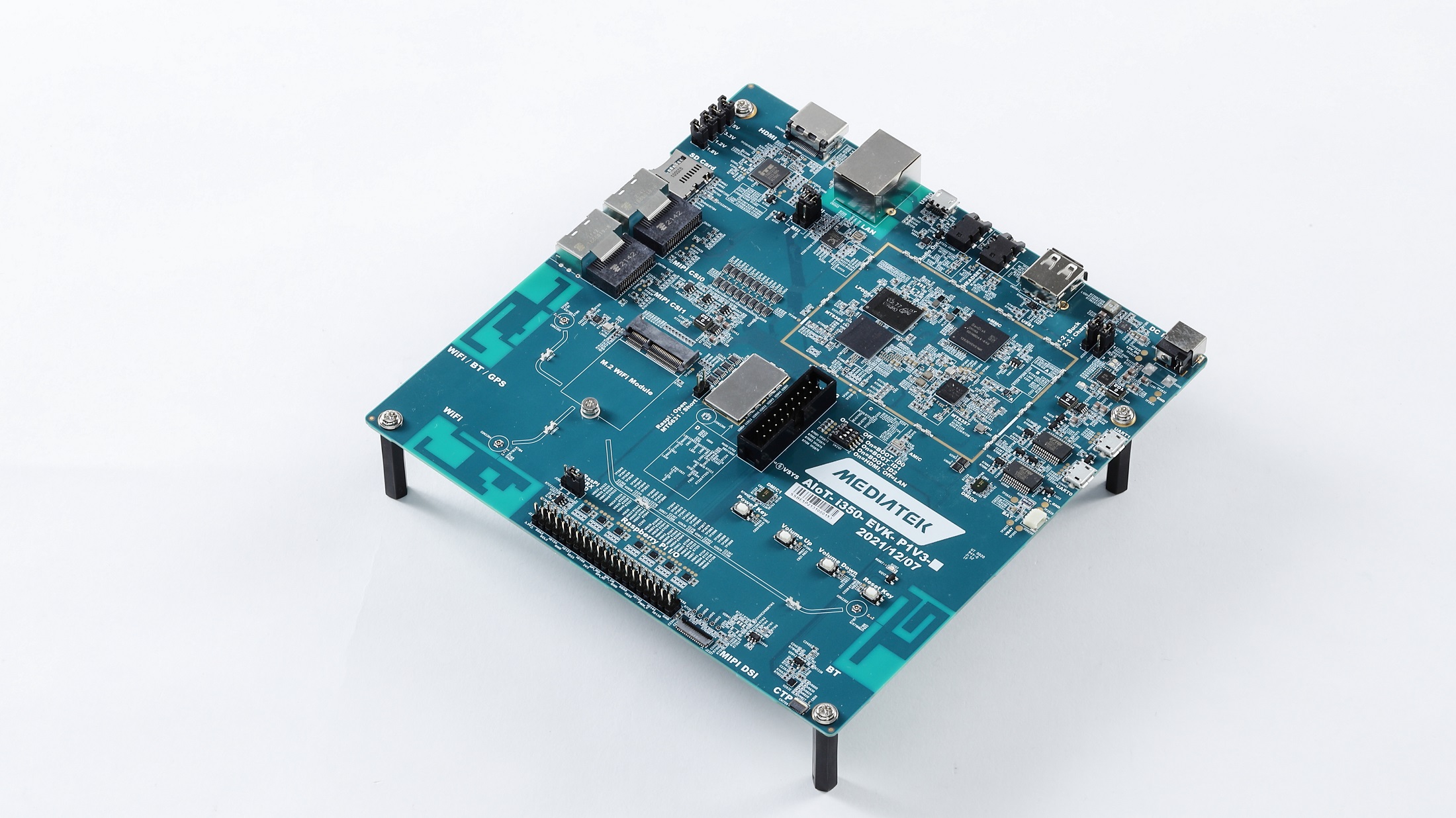
Top View of Genio 350-EVK
Board Block Diagram

Block Diagram of Genio 350-EVK and Support Status of IoT Yocto
Packing List
S.No |
Part Number or Marking |
Item Name |
Description |
Quantity |
|---|---|---|---|---|
1 |
AIoT-i350-EVK-P1V3 |
Genio 350 EVK main motherboard |
1 |
|
2 |
AIoT CAM DTB D1V2 |
AP1302 ISP Camera Board |
Camera sub-board using Onsemi AP1302 Image Sensor Processor |
2 |
3 |
AP-VISION- AR0430 |
Appletec AR0430 Camera Module |
Camera Module using Onsemi AR0430 BSI CMOS Digital Image Sensor, preconnected to AP1302 ISP Camera Board |
2 |
4 |
MT7663BS NGFF V10 |
AzureWave Wireless Module |
||
5 |
Mini-SAS cable |
Camera Cable |
2 |
|
6 |
TP7025C13 |
TFT LCM MODULE 7 LCM+TP |
LCD Module |
1 |
7 |
I350EVK-LCM FPC-R002 |
LCM FPC Cable |
1 |
|
8 |
12V AC adapter |
1 |
||
9 |
AC cable |
1 |
||
10 |
Plastic Standoffs |
4 |
||
11 |
Screw |
4 |
||
12 |
Jumper wires |
To jumper from AzureWave Wireless Module to PCB antennas |
2 |
Description of Kit Contents
Genio 350 EVK Main Motherboard
The image shows the main mother board and relevant IO.
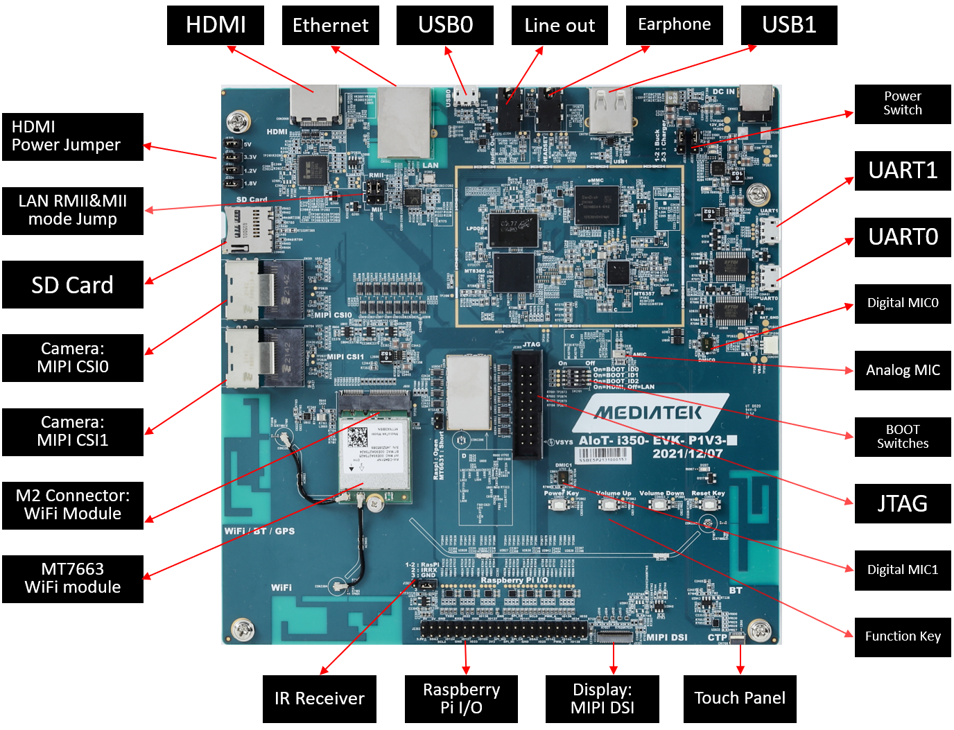
Genio 350-EVK main motherboard interfaces
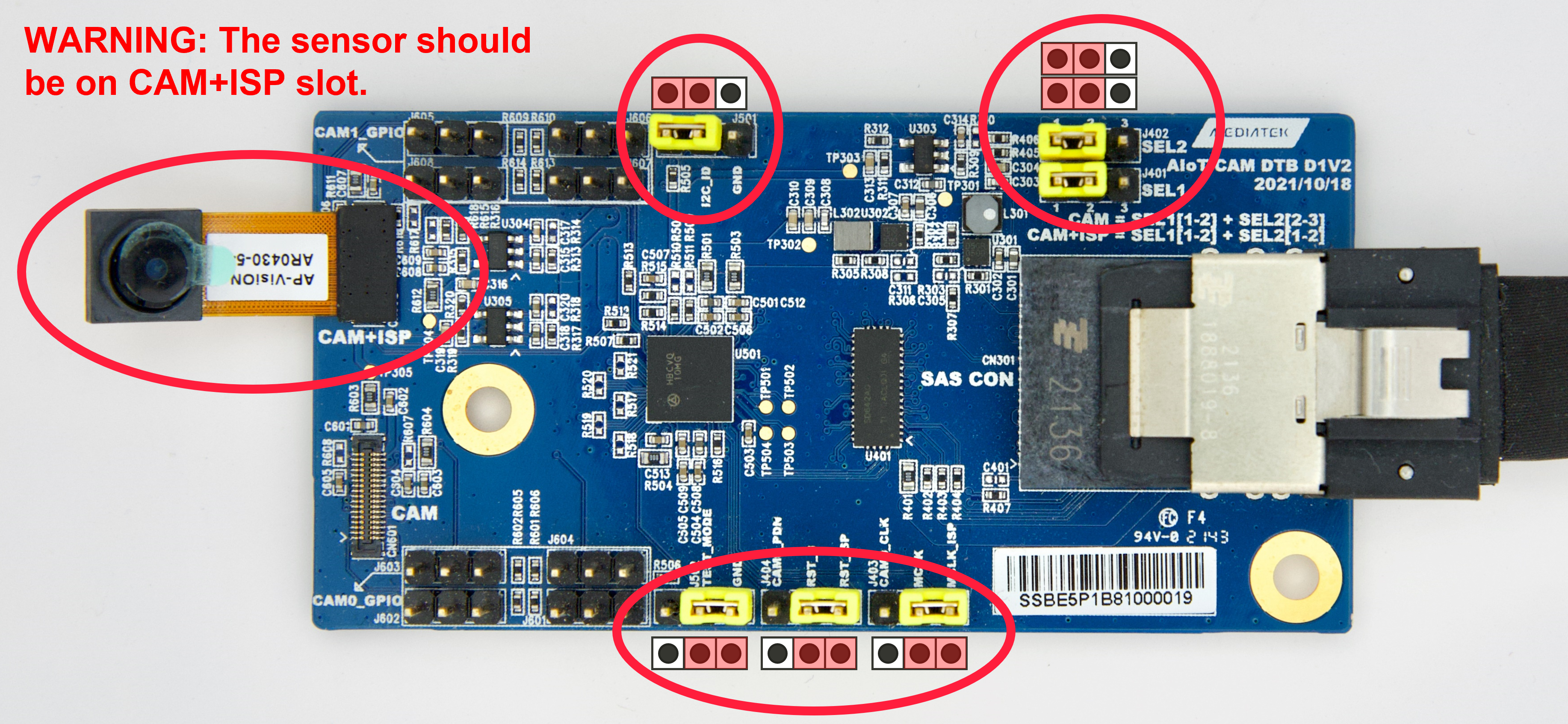
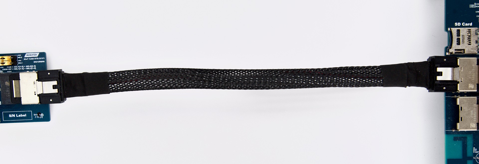
AP1302 ISP Camera Board, Appletec AR0430 Camera Module, and mini-SAS cable
Each AP1302 ISP Camera Board can be connected to the main mother board with a mini-SAS cable. An AP1302 ISP Camera Board supports two possible MIPI CSI paths:
Connect directly with the processor (MT8365) on the Genio 350 EVK main motherboard
Connect with the main board through an ISP (On-Semiconductor AP1302CSSL00SMGA0-DR)
These two MIPI paths are switched by a MIPI multiplexer (TI TS3DV642RUARQ1) which is controlled by the correct jumper selection and cabling. The small device pictured below is the Appletec AR0430 Camera Module and it features the OnSemi AR0430 image sensor.
AzureWave Wireless Module
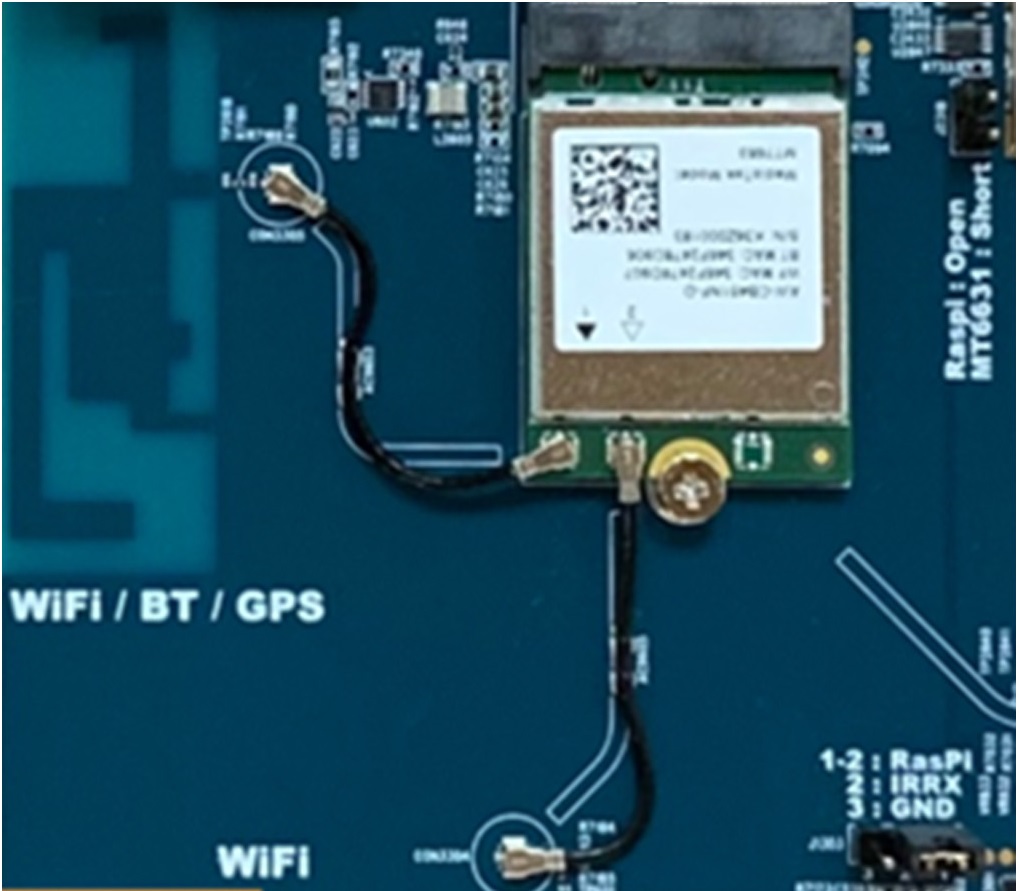
AzureWave Wireless Module
TFT LCM MODULE 7 LCM, Touch Panel, and LCM FPC Cable
A TFT LCM Module and touch panel can be connected to the Genio 350 EVK main motherboard with the LCM FPC Cable. Both are shown below. Please note that the demo covered in the Quick Start Guide does not use the LCM Module but rather an external HDMI Monitor.

LCM MODULE with FPC Cable
Board Feature Summary
At the current release, IoT Yocto enables the following board features:
Supported Board Features
MediaTek MT8365 SoC
MediaTek PMIC (MT6357)
3GB LPDDR4 RAM x 1 (Micron MT53E768M32D4DT-053)
64GB eMMC x 1 (SanDisk/Western Digital SDINBDA4_64G)
2.0mm DC Jack x 1 (for 12V DC Input)
Micro SD Card Slot x 1
Push Button x 4 (Power, Reset, Volume-Up and Volume-Down)
4-Lane DSI x 1
HDMI x 1
10/100 Ethernet x 1 (Shared with DPI Signal)
USB Device Port x 1 (Micro USB Connector)
USB Host Port x 1 (Type-A USB Connector)
3.5mm Earphone Jack x 1 (with Microphone Input)
3.5mm Line Out Audio Jack x 1
Analog Microphone x 1
Digital Microphone x 2
UART Port x 2 for Trace Log with USB to UART Bridge IC (Micro USB Connector x 2)
I2C Capacitive Touch Pad
4-Data Lane CSI x 2 (SAS SFF-8087 Connector)
M.2 Slot x 1 (for AzureWave AW-CB451NF WiFi Module)
40-Pin 2.54mm Pin Header x 1 (for Raspberry Pi like I/O Interface)
Unsupported Board Features
3-bit DIP Switch for Boot ID
2-Pin 2.54mm Jumper (for IrDA Receiver)
Battery Charger
MT6631 Bluetooth/Wi-Fi/GPS/FM
SPDIF In/Out
Bluetooth function on AzureWave AW-CB451NF is not supported
Important
IoT Yocto only provide proprietary BlueDroid stacks on MT7663.
FTDI Board Control
The Genio 350-EVK has two FTDI chips connected to the UART0 (CON461) port and to the UART1 (CON462) port. They are both able to control the power (PWRKEY), reset (SYSRST), and download (KPCOL0) lines.
FTDI GPIO Line |
Function |
|---|---|
0 |
Power (PWRKEY) |
1 |
Reset (SYSRST) |
2 |
Download (KPCOL0) |
