IoT Yocto BSP & Boot Architecture
This section describes the system booting architecture and the BSP images information at each boot stage.
The BSP(board support package) has the following booting architecture:
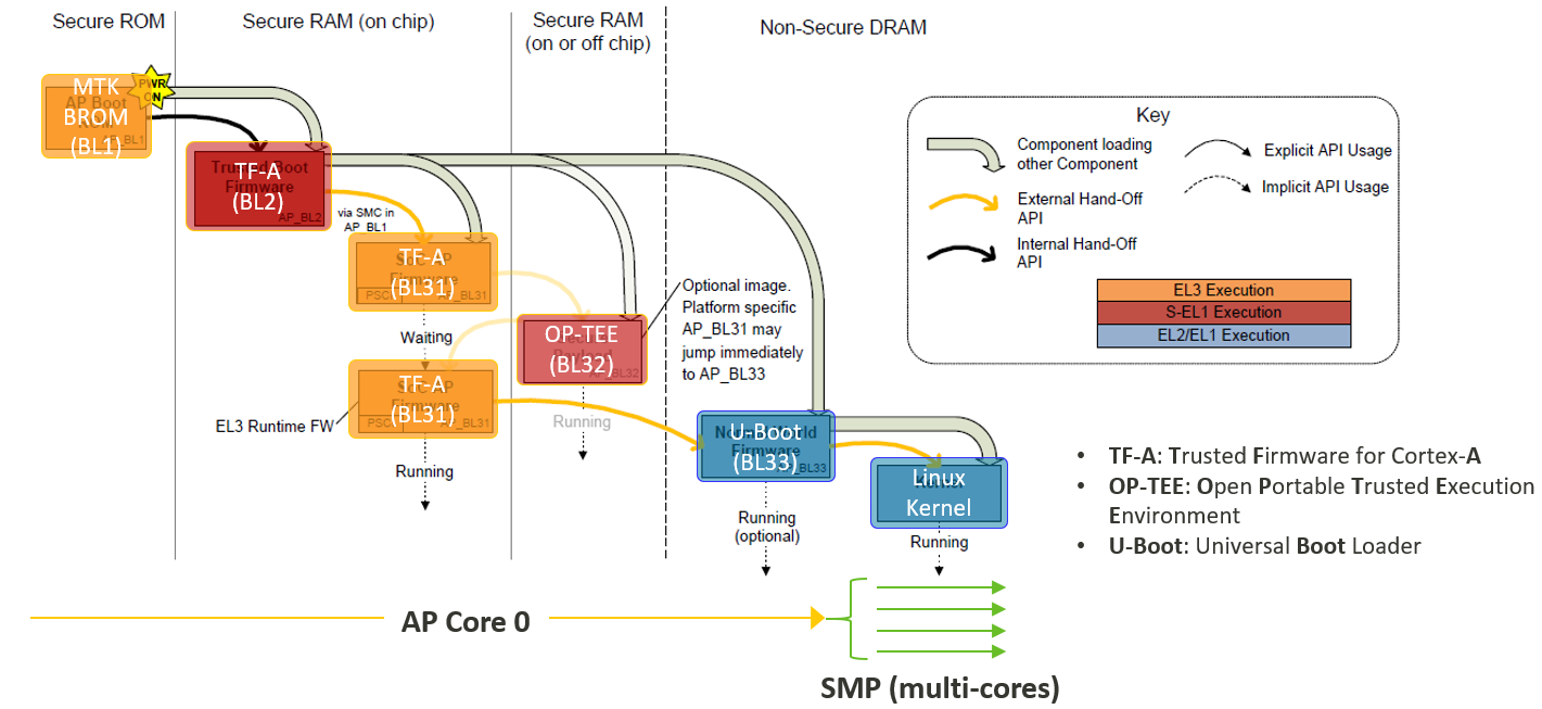
IoT Yocto BSP Boot Architecture
MediaTek SoC ROM Code
The MediaTek SoC ROM code will try to boot from different media:
eMMC
USB
UFS (MT8395 only)
The IoT Yocto only allows to boot from embedded MultiMedia Card (eMMC) and Universal Flash Storage (UFS). Universal Serial Bus (USB) is only used as part of the image flashing process but cannot be used alone to boot to a Linux userspace.
Please refer to the functional block and IoT Yocto support status for hardware features that IoT Yocto enables:
EMMC Boot
When the SoC boots, it chooses which media to boot from. If it chooses eMMC boot, the boot ROM looks at the first boot partition for a second stage bootloader.
In case the ROM code fails to find a valid boot partition or valid second stage bootloader, it will automatically go into USB Boot.
UFS Boot
MT8395 provides support to boot from UFS storage. However, the prebuilt Genio 1200-EVK image does not provide such support because Genio 1200-EVK does not have UFS storage.
Please refer to the mt8395-evb-ufs in
meta-mediate-bsp layer
to know how to configure for UFS booting.
USB Boot
In IoT Yocto, the ROM code USB boot is used only for flashing.
BL2 (TF-A)
The second stage bootloader is based on Trusted Firmware A (TF-A). The IoT Yocto BSP ships pre-built binaries for second stage bootloaders.
We base the second stage bootloader on Trusted Firmware A (TF-A). IoT Yocto BSP includes pre-built binaries for second stage bootloaders.
BL2 first initializes the hardware:
Initialize the system timer
Initialize and turn on the phase locked loops (PLLs)
Initialize the Power Management IC (PMIC) wrap component in order to be able to talk to the PMIC
Sends a baseband power-up signal to the PMIC to notify him of a successful power up.
Initialize the Double Data Rate (DDR) SDRAM
Initialize the eMMC
Once BL2 initializes the hardware, it will read 4MB of memory from the bootloaders partition
of the eMMC. You can retrieve the offset of the bootloaders partition using the TF-A
application programming interface (API) get_partition_entry(partition_name).
The API provides the entry of the bootloaders partition to find the fip.bin file.
This partition section should contain the fip.bin file.
Firmware Image Package (FIP) is a packaging format used by TF-A to package firmware images. In IoT Yocto the FIP contains BL31, BL32, BL33 and optionally some certificates when secure boot is enabled.
BL2 will read the FIP package and execute each of the binary it contains.
BL31 (TF-A)
TF-A provides BL31, which provides the Power State Coordination Interface (PSCI) routines. Once the system loads BL33, it no longer uses BL2. However, BL31 remains in DDR until you power off or reboot.
Once BL31 completes initialization, it will jump back to BL2.
Source repository: https://gitlab.com/mediatek/aiot/bsp/trusted-firmware-a
BL32 (OP-TEE)
BL32 is the secure OS that runs in TrustZone. IoT Yocto BSP is using by default Open Portable Trusted Execution Environment (OP-TEE) trusted OS.
Like BL31, OP-TEE OS stays in DDR until a power off or a reboot.
Source repository: https://gitlab.com/mediatek/aiot/bsp/optee-os
BL33 (U-Boot)
U-Boot is the third and last stage bootloader in the IoT Yocto boot architecture. It is used to load and boot the kernel from the kernel partition.
In IoT Yocto the kernel must be encapsulated into a Flattened Image Tree (FIT) image. The FIT image contains the kernel binary, a Device Tree Blob (DTB), and optionally some Device Tree Blob Overlay (DTBO).
U-Boot uses Device Tree Blob Overlays (DTBOs) to provide optional features to a board, such as cameras,
displays, or any daughter boards. U-Boot checks its boot_conf
environment variable to determine which overlay (if any) it should load and
merge with the main DTB. To merge a DTBO, you need to change boot_conf using the following format:
boot_conf=#conf-[platform_dtb_name]#conf-[feature1_dtbo_name]#conf-[feature2_dtbo_name]
For example if you would like to add a DTBO used for Display Serial Interface (DSI) panel support to Genio 350-EVK (dtbo name: display-dsi.dtbo).
boot_conf=#conf-mediatek_mt8365-evk.dtb#conf-display-dsi.dtbo
There are 2 methods that developers can configure boot_conf to merge DTBOs by U-Boot in IoT Yocto.
modify it during the Yocto build system by setting the following variable:
KERNEL_DEVICETREE_OVERLAYS_AUTOLOAD += "display-dsi.dtbo"
modify it with using genio-tools
genio-flash --load-dtbo display-dsi.dtbo
Besides, it is possible to set the boot_conf variable from the U-Boot shell,
target Linux system, or the u-boot-initial-env file directly.
There are several ways to modify boot_conf.
Writing to the
u-boot-initial-envfile presented in the deploy image folder before flashing image. (Not recommended because it may be overwritten by Bitbake later on)In the U-Boot shell:
setenv boot_conf "you-boot-env-var"; saveenv
In the target Linux system:
fw_setenv boot_conf "you-boot-env-var"
User can also use U-Boot to flash (via Fastboot), or to boot the kernel and/or rootfs using a USB connection. Please refer to the board’s documentation to know which features your specific board supports.
Boot from External Storage
In MediaTek’s IoT Yocto platforms, the Boot ROM (BROM) dose not natively support booting from removable storage types such as USB, SD Card, or Ethernet. BROM supports only main storage like eMMC or UFS, depends on the hardware capability of each Genio platforms. However, it is still possible to boot Linux from these storage types by leveraging the common features provided by U-Boot (BL33). For more detail, please refer to Boot from External Storage chapter.
Source repository: https://gitlab.com/mediatek/aiot/bsp/u-boot
Linux
The Linux kernel is the main OS running. It will load the root filesystem (rootfs) and starts running the init process.
The following versions of Linux are currently supported on IoT Yocto:
Kernel version |
Branch name |
|---|---|
v5.4 |
|
v5.10 |
|
v5.15 |
|
By default, the system builds the latest stable Linux release supported by IoT Yocto.
If you want to use an older supported kernel, set the PREFERRED_VERSION_linux-mtk
variable in your local.conf.
For example if you want to use the v5.4 branch you can set:
PREFERRED_VERSION_linux-mtk = "5.4%"