YUV Sensor (MediaTek Imgsensor)
Note
All command operations presented in this chapter are based on Genio 1200-EVK and Onsemi AP1302 ISP and AR0830 sensor. You might get different operation results depending on the platform you use.
Camera Daughter Board
The YUV camera DTB for Genio 1200-EVK is CAM DTB-D6.
It contains an Onsemi AP1302 ISP and an AR0830 Sensor.
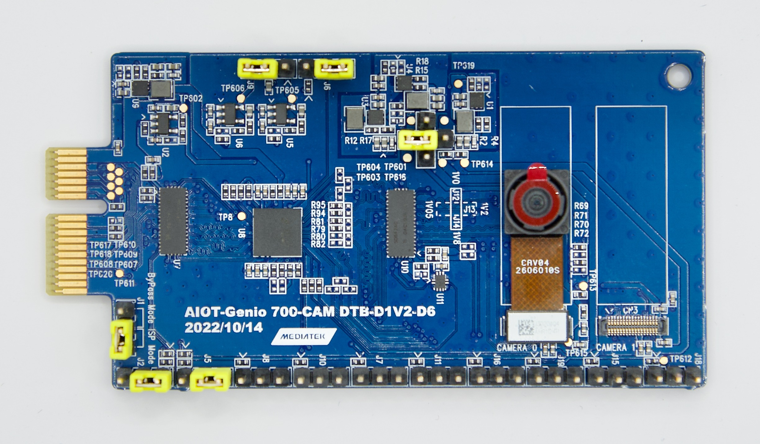
Camera DTB D6 - Onsemi AP1302 ISP and AR0830 Sensor
Connect The Camera To The EVK
There are 3 MIPI-CSI sockets on Genio 1200-EVK, which are CSI0, CSI1, and CSI2.
In the following figure, the camera DTB is connected to the CSI0 socket.
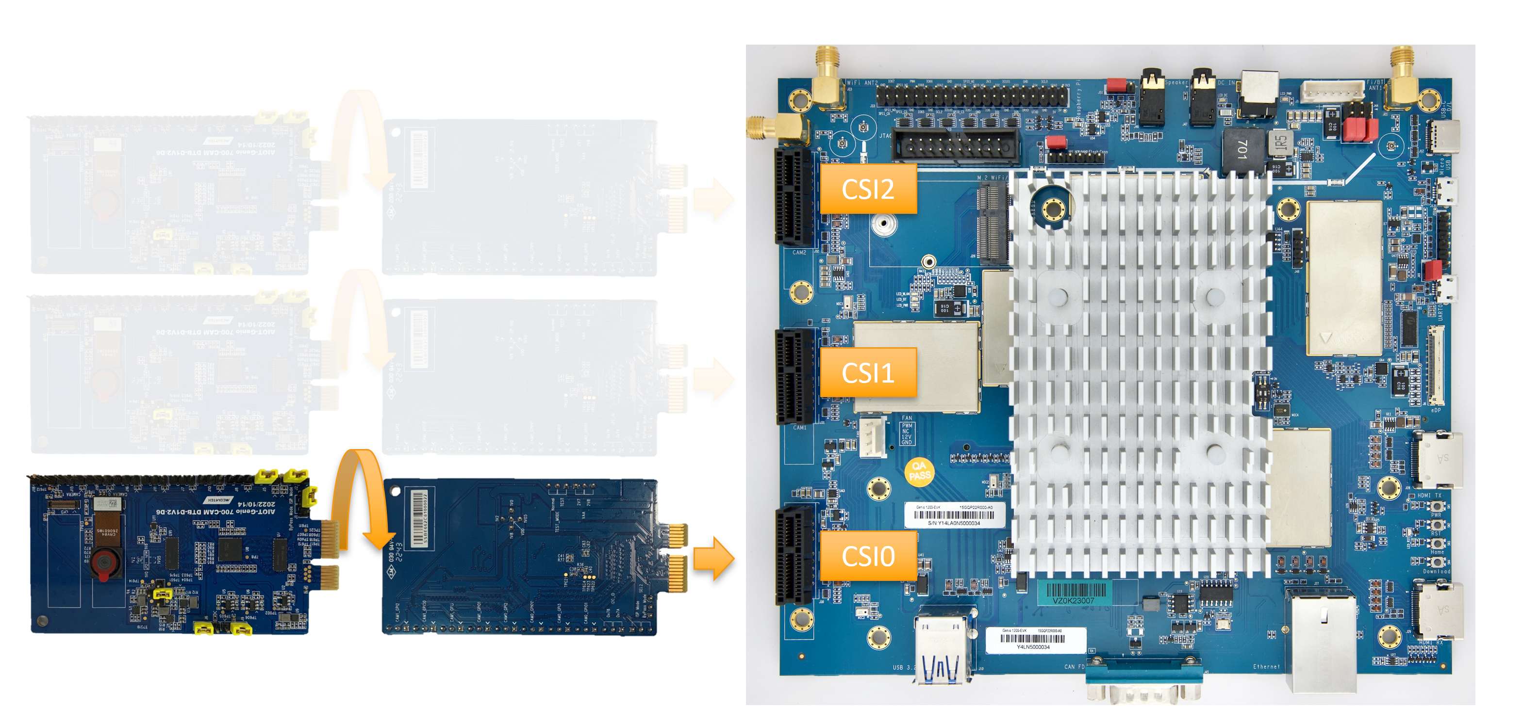
Connect Camera DTB D6 to Genio 1200-EVK
The hardware connection is AR0830 ---> AP1302 ---> MIPI-CSI On EVK.
The camera daughter board can be configured in ISP mode and Bypass mode.
In ISP mode, the images from the AR0830 camera module are passed to AP1302 ISP before being received by the EVK.
In Bypass mode, the images from the AR0830 camera module are transferred to the EVK directly.
By default, IoT Yocto only supports ISP mode.
To configure the camera DTB D6 to ISP mode, you MUST set 6 jumpers and 1 camera sensor as shown in the figure below. The jumpers MUST be correctly set and the camera sensor MUST be connected to the CAMERA 0 slot.
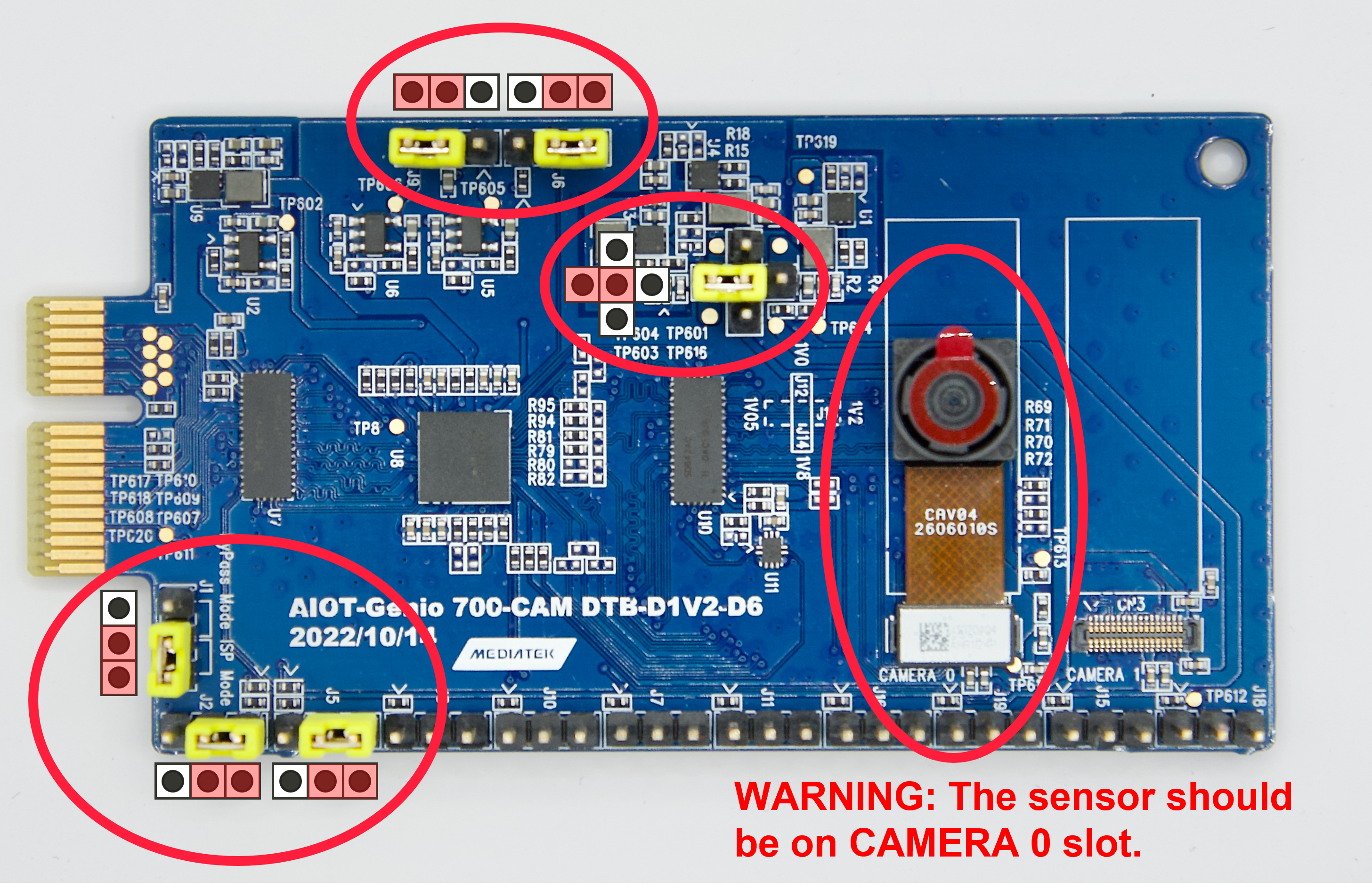
Camera DTB D6 - ISP mode
Warning
Please make sure all the above settings, including the jumpers, camera slot, and MIPI-CSI socket, are correct. Otherwise, the I2C connection between the sensor, ISP, and SoC will fail.
Select Camera Device Tree Blob Overlay
The camera device is inactive by default, so the kernel has to load a specific device tree blob overlay to enable it. Please refer to the bl33 (u-boot) section for more details.
Platform |
CSI0 |
CSI1 |
CSI2 |
DTBO |
Usage |
|---|---|---|---|---|---|
Genio 1200-EVK |
AP1302+ AR0830 |
x |
x |
camera-ar0830-ap1302-csi0.dtbo |
Enable 4-lane CAM-DTB-D6 w/ Onsemi AR0830 on CSI0 |
Genio 1200-EVK |
AP1302+ AR0830 (2 lane) |
x |
x |
camera-ar0830-ap1302-2lanes-csi0.dtbo |
Enable 2-lane CAM-DTB-D6 w/ Onsemi AR0830 on CSI0 |
Genio 1200-EVK |
x |
AP1302+ AR0830 |
x |
camera-ar0830-ap1302-csi1.dtbo |
Enable 4-lane CAM-DTB-D6 w/ Onsemi AR0830 on CSI1 |
Genio 1200-EVK |
x |
x |
AP1302+ AR0830 |
camera-ar0830-ap1302-csi2.dtbo |
Enable 4-lane CAM-DTB-D6 w/ Onsemi AR0830 on CSI2 |
genio-flash --list-dtbo
List of available DTBO:
- camera-ar0830-ap1302-2lanes-csi0.dtbo
- camera-ar0830-ap1302-csi0.dtbo
- camera-ar0830-ap1302-csi1.dtbo
- camera-ar0830-ap1302-csi2.dtbo
- ...
genio-flash --load-dtbo camera-ar0830-ap1302-csi0.dtbo --load-dtbo gpu-mali.dtbo --load-dtbo apusys.dtbo --load-dtbo video.dtbo
Warning
Please select the DTBO according to the CSI slot to which the camera sensor is connected.
For example, if the camera is connected to the CSI0 slot, please load the dtbo camera-ar0830-ap1302-csi0.dtbo.
Otherwise, the camera initialization will fail.
Supported Formats And Sizes
Platform |
Sensor |
Stream Type |
Size |
Frame rate |
Format |
MIPI Lanes |
|---|---|---|---|---|---|---|
Genio 1200-EVK |
Onsemi AP1302 & AR0830 |
Preview |
1920x1080 |
30 |
UYVY |
4 |
Genio 1200-EVK |
Onsemi AP1302 & AR0830 |
Preview |
2560x1440 |
30 |
UYVY |
4 |
Genio 1200-EVK |
Onsemi AP1302 & AR0830 |
Preview |
3840x2160 |
24 |
UYVY |
4 |
Genio 1200-EVK |
Onsemi AP1302 & AR0830 |
Preview |
1920x1080 |
30 |
UYVY |
2 |
Genio 1200-EVK |
Onsemi AP1302 & AR0830 |
Preview |
2560x1440 |
30 |
UYVY |
2 |
Genio 1200-EVK |
Onsemi AP1302 & AR0830 |
Preview |
3840x2160 |
12 |
UYVY |
2 |
Note
The supported format, resolution, and frame rate are related to the capability of the sensor and SoC.
V4L2 Device Node
Camera ISP is a complicated feature that has a large number of device nodes. The camera ISP driver creates 123 video devices in total.
MTK-ISP-DIP-V4L2has 68 devicesmtk-camhas 54 devicesmtk-v4l2-camerahas 1 device
MTK-ISP-DIP-V4L2 and mtk-cam are used by the camera ISP middleware.
The user can just focus on mtk-v4l2-camera which is for streaming.
v4l2-ctl --list-devices
...
mtk-cam (platform:16000000.camisp):
(54 video devices)
/dev/media2
mtk-v4l2-camera (platform:mtkcam0):
/dev/video74
Launch Camera
The V4L2 nodes with the name mtk-v4l2-camera can be used for streaming.
For the YUV sensor, there’s only 1 V4L2 device which is for the preview stream.
The user can find the devices by the following command:
v4l2-ctl --list-device
mtk-v4l2-camera (platform:mtkcam0):
        /dev/video74
cat /sys/class/video4linux/video74/name
mtk-v4l2-camera@0-Preview
Important
The above v4l2 device node number is for example. The node number may change every time the system boots.
To quickly fetch the correct node and assign the environment variable:
declare -a VIDEO_DEV=(`v4l2-ctl --list-devices | grep mtk-v4l2-camera -A 1 | grep video | tr -d "\n"`)
printf "Preview Node\t= ${VIDEO_DEV[0]}\n"
Preview Node    = /dev/video74
Section Supported formats and Sizes shows the supported formats and sizes.
The user can also use the v4l2 utility, v4l2-ctl, to list formats.
v4l2-ctl -d ${VIDEO_DEV[0]} --list-formats-ext
ioctl: VIDIOC_ENUM_FMT
        Type: Video Capture Multiplanar

        [0]: 'UYVY' (UYVY 4:2:2)
                Size: Discrete 1920x1080
                        Interval: Discrete 0.033s (30.000 fps)
        ...
To launch the camera, the user can use v4l2-ctl, gst-launch-1.0, or other V4L2 applications.
Use
v4l2-ctlv4l2-ctl -d ${VIDEO_DEV[0]} --set-fmt-video=width=1920,height=1080,pixelformat=UYVY --stream-mmap --stream-count=10 --stream-to=/tmp/ap1302.yuv --verboseUse
gst-launch-1.0gst-launch-1.0 v4l2src device=${VIDEO_DEV[0]} ! video/x-raw,width=1920,height=1080,format=UYVY ! v4l2convert output-io-mode=dmabuf-import ! video/x-raw,width=1280,height=720 ! waylandsink sync=false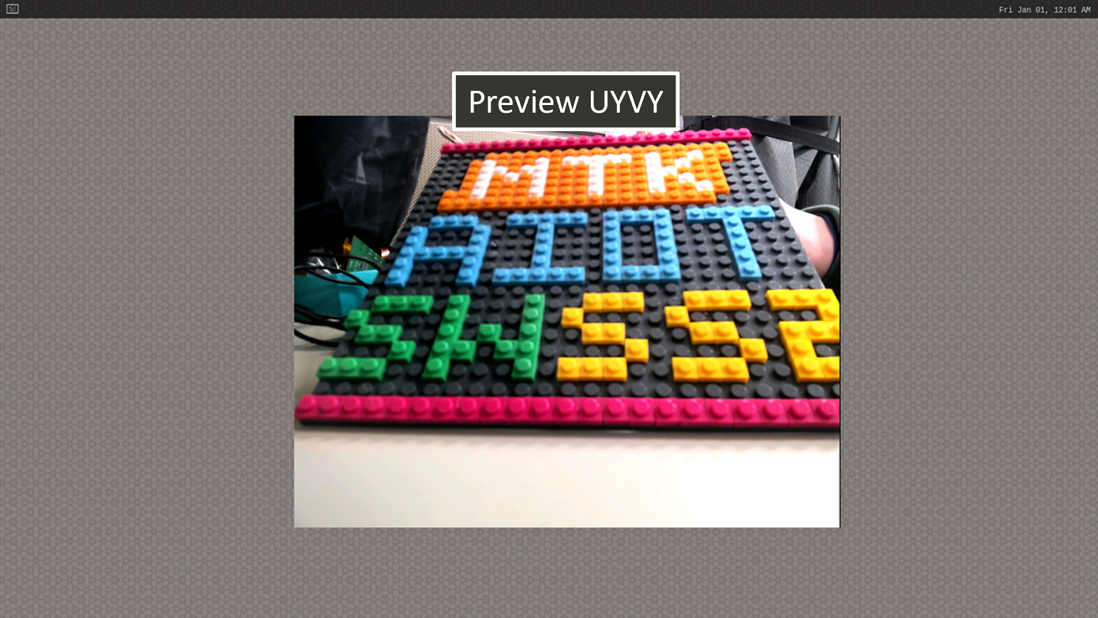
Show Preview stream on Weston
Note
To use MediaTek video codec and MDP hardware, the user has to load video.dtbo. For more details, please refer to Genio 1200-EVK Video Codec.
Sensor Launch Time
In our camera operation sequence, we follow the steps below:
Open Camera
Power on the sensor
Release the reset pin
Configure the sensor settings
Stream on the sensor
Close Camera
Stream off the sensor
Hold the reset pin
Power off the sensor
When using the AP1302 ISP, it is necessary to download a specific firmware binary during initialization. The launch time of the camera depends on the size of the binary file. The log provided below illustrates the start-up process of the AP1302 ISP and displays the corresponding launch time.

The presented log provides an overview of the AP1302 ISP start-up process and focuses on the launch time, which primarily measures the duration it takes to transmit the firmware through I2C at a speed of 400KHz.