Virtual Channel (V4L2 Sensor)
Important
All the bash commands shown here are based on Genio 720-EVK, MAX96724 EVKit, and AG190H. For Genio 520-EVK, users can follow the same steps to perform the setup by changing the name from 720 to 520. You might get different operation results depending on the platform you use.
This chapter shows how to use virtual channel sensors (e.g., SerDes) under V4L2 Sensor architecture on Genio 520/720-EVK.
Introduction to Virtual Channel and SerDes
Virtual Channel
The MIPI Camera Serial Interface (CSI) is a standard communication protocol used primarily for transmitting data between cameras and host processors. One of the key features of the MIPI CSI protocol is Virtual Channel. This feature is particularly important as it enhances the flexibility and scalability of camera systems in embedded applications.
Virtual channels are logical channels that allow multiple video streams to be transmitted over a single physical connection. This means that a single MIPI CSI interface can handle data from multiple camera sources simultaneously, without the need for additional physical lanes. Each virtual channel is identified by a unique ID, which is used to distinguish between different streams of data.
When a camera captures an image, the data is packaged into frames and tagged with the virtual channel ID. The host processor (e.g., MT8371, MT8391) then uses these IDs to route and process each stream appropriately. This process is seamless and transparent to the end-user but requires careful configuration and synchronization to ensure data integrity and timely delivery.
The benefits of virtual channels include:
Efficiency: Maximize the use of the physical lanes available, allowing for more data throughput without the need for extra hardware.
Flexibility: Transmit multiple streams from different cameras, which can be useful in advanced applications that require data from multiple sensors.
Cost-effective: Reduce the number of physical connections needed for multiple camera setups to lower the overall system cost and complexity.
SerDes
SerDes, short for Serializer/Deserializer, is a crucial technology used in high-speed communications. It facilitates the transfer of data over a differential pair of wires or a single high-speed data lane. This technology is fundamental in various applications, including data centers, consumer electronics, automotive systems, and telecommunications.
The serializer converts parallel data into a serial stream, reducing the number of data paths and thus minimizing the number of wires needed for data transmission. Conversely, the deserializer performs the opposite function. It converts the serial data back into parallel form, making it usable by the receiving system.
In a typical SerDes setup, the serializer (e.g., MAX96705, MAX9295) receives parallel data from the data source along with a clock signal. It aligns the data bits into a serial stream and sends it over a high-speed transmission medium. At the receiving end, the deserializer (e.g. MAX9286, MAX96724) extracts the clock and realigns the incoming serial data into parallel format. Finally, the deserializer transmits the parallel data to the host receiver.
The benefits of using SerDes include:
Reduced Complexity: By minimizing the number of physical connections required for data transmission, SerDes simplifies board layout and reduces hardware complexity.
Increased Speed: Enables high-speed data transmission that is essential for modern applications, such as video streaming, high-performance computing, and high-speed networking.
Improved Signal Integrity: Helps in maintaining the quality of the signal over longer distances by using differential signaling.
Camera Daughter Board
The SerDes camera DTB for Genio 520/720-EVK is IoT-CAM-DTB-D10.
It contains a MAX96724-BAK-EVK# and a GMSL EVKIT RPi Adaptor.
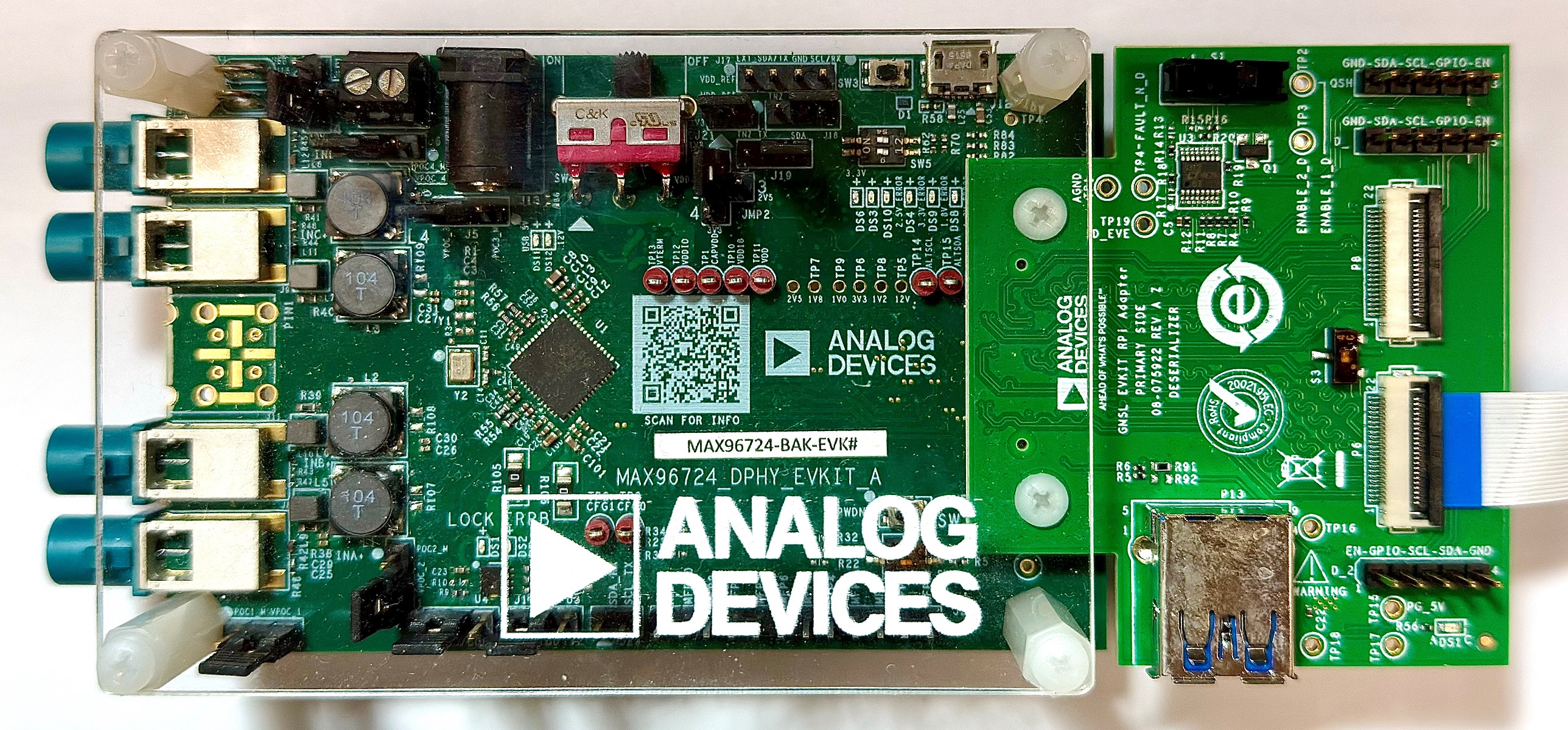
Camera DTB D10 - MAX96724-BAK-EVK# and GMSL EVKIT Rpi Adaptor
The camera module is ABEO AG190H.
It contains an OmniVision OX03C sensor, an OmniVision OAX4000 ISP, and an ADI MAX9295 serializer.
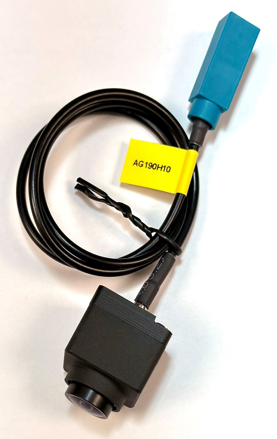
Camera Module - ABEO AG190H
Connect the SerDes to the EVK
There are 2 MIPI-CSI sockets on Genio 720-EVK, which are CAM0 and CAM1.
In the following figure, the camera DTB is connected to the CAM0 socket.
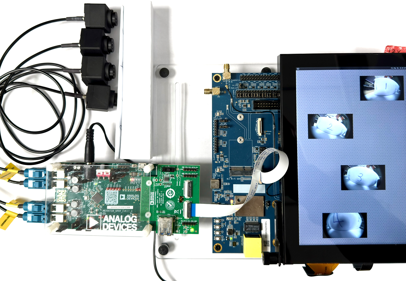
Genio 720-EVK with 1x MAX96724-BAK-EVK and 4x ABEO AG190H sensors
The FPC cable between the Genio 720-EVK and MAX96724 EVK MUST be twisted to ensure correct orientation.
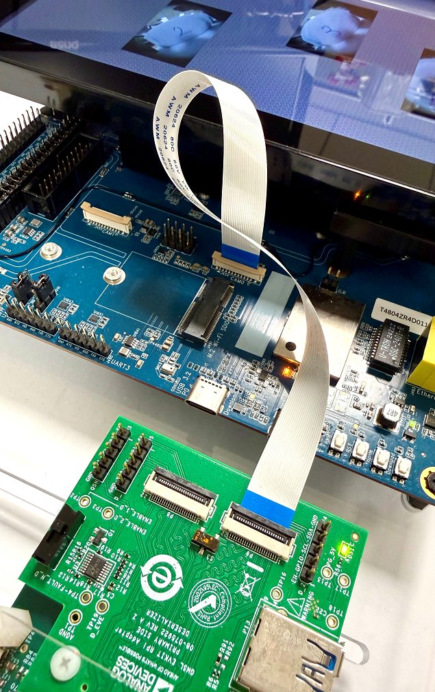
FPC Connection Between Genio 720-EVK and MAX96724-BAK-EVK
The hardware connection is AG190H ---> MAX96724-BAK-EVK ---> MIPI-CSI On Genio 720-EVK.

Hardware Block Diagram of Single SerDes and SoC
After finishing the above steps, the hardware connection is complete.
Configure the MAX96724 EVKIT
The MAX96724 EVKIT has various flexible configurations, including jumpers, switches, and programmable settings. To replicate the supported configuration, users MUST follow the steps below to configure the MAX96724 EVK.
GMSL EVKIT RPi Adaptor
Set switch
S1toCAM2.Set switch
S3to the left.Connect the FPC cable to
P6 (CAM2).
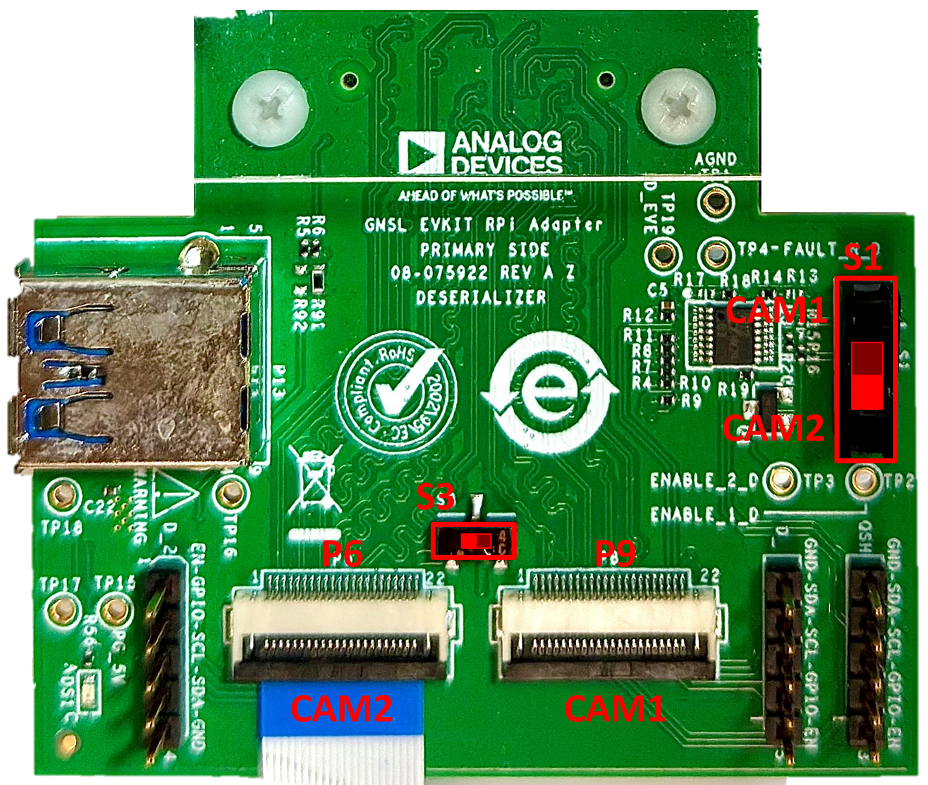
The Setting of GMSL EVKIT RPi Adaptor
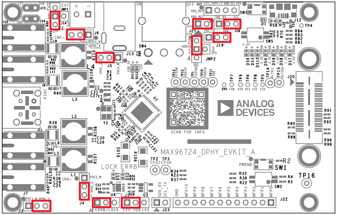
MAX96724-BAK-EVK
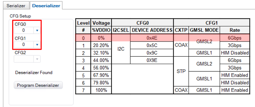
Select Camera Device Tree Blob Overlay
The camera device is inactive by default, so the kernel must load a specific device tree blob overlay to enable it. Please refer to the bl33 (u-boot) section for how to load DTBO.
The following table shows the supported SerDes DTBO in V4L2 sensor architecture.
Platform |
CSI0 |
CSI1 |
DTBO |
Usage |
|---|---|---|---|---|
Genio 520/720-EVK |
MAX96724 + 4x AG190H |
x |
camera-ag190h-max96724-csi0-std.dtbo |
Enable 4-lane ADI MAX96724 EVK w/ 4x ABEO AG190H on CAM0 using standard V4L2 driver |
Genio 520/720-EVK |
x |
MAX96724 + 2x AG190H |
camera-ag190h-max96724-csi1-std.dtbo |
Enable 4-lane ADI MAX96724 EVK w/ 2x ABEO AG190H on CAM0 using standard V4L2 driver |
Genio 520/720-EVK |
MAX96724 + 4x AG190H |
MAX96724 + 2x AG190H |
camera-ag190h-max96724-dual-std.dtbo |
Enable 4-lane ADI MAX96724 EVK w/ 4x 2x ABEO AG190H on CAM0 and CAM1 using standard V4L2 driver |
genio-flash --list-dtbo
List of available DTBO:
camera-ag190h-max96724-csi0-std.dtbo
camera-ag190h-max96724-csi1-std.dtbo
camera-ag190h-max96724-dual-std.dtbo
...
genio-flash --load-dtbo camera-ag190h-max96724-csi0-std.dtbo
Media Device
The media device represents the internal topology of a media system like ISP. Topology settings, including links, pads, and entities, can be configured through the media device. Therefore, the first step is to find the target media device node.
export MEDIA_DEV=$(v4l2-ctl -z platform:$(basename `find /sys/bus/platform/devices/ -name "*seninf-top"`) --list-devices | grep media)
echo ${MEDIA_DEV}
/dev/media1
Warning
The assigned node number for the media device may vary depending on the sequence of the probing process during the boot-up phase. As such, it is crucial to ensure the accuracy of the media device node before using the camera.
Video Device
The video device is the interface for users to obtain the images. On Genio 520/720-EVK, they are called 1a09[2-7]000\.camsv[2-7] video stream.
media-ctl is a useful tool to list video devices.
declare -a VIDEO_DEV=($(for i in `find /sys/bus/platform/devices/ -name "*camsv*" | sort`; do media-ctl -d ${MEDIA_DEV} --entity "`basename $i` video stream" ; done))
echo ${VIDEO_DEV[*]}
/dev/video5 /dev/video6 /dev/video7 /dev/video8 /dev/video9 /dev/video10
Warning
The assigned node number for the video device may vary depending on the sequence of the probing process during the boot-up phase. As such, it is crucial to ensure the accuracy of the video device node before using the camera.
Launch Camera
The initial step is to link all the necessary components within the media device. The structure of the YUV camera pipeline is quite straightforward. It consists of only three components: the sensor, SENINF, and CAMSV.
# Set the name of MAX96724
MAX96724_1_NAME="max96724 7-0027:0"

media-ctl -d ${MEDIA_DEV} -l "'${MAX96724_1_NAME}':0 -> 'seninf-0':0 [1]"
media-ctl -d ${MEDIA_DEV} -l "'seninf-0':1 -> '1a092000.camsv2':0 [1]"
media-ctl -d ${MEDIA_DEV} -l "'seninf-0':2 -> '1a093000.camsv3':0 [1]"
media-ctl -d ${MEDIA_DEV} -l "'seninf-0':3 -> '1a094000.camsv4':0 [1]"
media-ctl -d ${MEDIA_DEV} -l "'seninf-0':4 -> '1a095000.camsv5':0 [1]"
The second step is to assign the correct format and size to each component within the camera pipeline.
media-ctl -d ${MEDIA_DEV} -V "'${MAX96724_1_NAME}':0 [fmt:YUYV8_1X16/1920x1080]"
media-ctl -d ${MEDIA_DEV} -V "'seninf-0':1 [fmt:YUYV8_1X16/1920x1080]"
media-ctl -d ${MEDIA_DEV} -V "'seninf-0':2 [fmt:YUYV8_1X16/1920x1080]"
media-ctl -d ${MEDIA_DEV} -V "'seninf-0':3 [fmt:YUYV8_1X16/1920x1080]"
media-ctl -d ${MEDIA_DEV} -V "'seninf-0':4 [fmt:YUYV8_1X16/1920x1080]"
media-ctl -d ${MEDIA_DEV} -V "'1a092000.camsv2':1 [fmt:YUYV8_1X16/1920x1080]"
media-ctl -d ${MEDIA_DEV} -V "'1a093000.camsv3':1 [fmt:YUYV8_1X16/1920x1080]"
media-ctl -d ${MEDIA_DEV} -V "'1a094000.camsv4':1 [fmt:YUYV8_1X16/1920x1080]"
media-ctl -d ${MEDIA_DEV} -V "'1a095000.camsv5':1 [fmt:YUYV8_1X16/1920x1080]"
Lastly, to activate the camera, the user can use v4l2-ctl, gst-launch-1.0, or other V4L2 applications.
Use
v4l2-ctlv4l2-ctl -d ${VIDEO_DEV[0]} --set-fmt-video=width=1920,height=1080,pixelformat=YUYV --stream-mmap --stream-count=10 --stream-to=/tmp/serdes_vc0.yuv --verbose v4l2-ctl -d ${VIDEO_DEV[1]} --set-fmt-video=width=1920,height=1080,pixelformat=YUYV --stream-mmap --stream-count=10 --stream-to=/tmp/serdes_vc1.yuv --verbose v4l2-ctl -d ${VIDEO_DEV[2]} --set-fmt-video=width=1920,height=1080,pixelformat=YUYV --stream-mmap --stream-count=10 --stream-to=/tmp/serdes_vc2.yuv --verbose v4l2-ctl -d ${VIDEO_DEV[3]} --set-fmt-video=width=1920,height=1080,pixelformat=YUYV --stream-mmap --stream-count=10 --stream-to=/tmp/serdes_vc3.yuv --verbose
Use
gst-launch-1.0gst-launch-1.0 v4l2src device=${VIDEO_DEV[0]} ! video/x-raw,width=1920,height=1080,format=YUY2 ! v4l2convert output-io-mode=dmabuf-import ! video/x-raw,width=640,height=480 ! waylandsink sync=false & gst-launch-1.0 v4l2src device=${VIDEO_DEV[1]} ! video/x-raw,width=1920,height=1080,format=YUY2 ! v4l2convert output-io-mode=dmabuf-import ! video/x-raw,width=640,height=480 ! waylandsink sync=false & gst-launch-1.0 v4l2src device=${VIDEO_DEV[2]} ! video/x-raw,width=1920,height=1080,format=YUY2 ! v4l2convert output-io-mode=dmabuf-import ! video/x-raw,width=640,height=480 ! waylandsink sync=false & gst-launch-1.0 v4l2src device=${VIDEO_DEV[3]} ! video/x-raw,width=1920,height=1080,format=YUY2 ! v4l2convert output-io-mode=dmabuf-import ! video/x-raw,width=640,height=480 ! waylandsink sync=false &
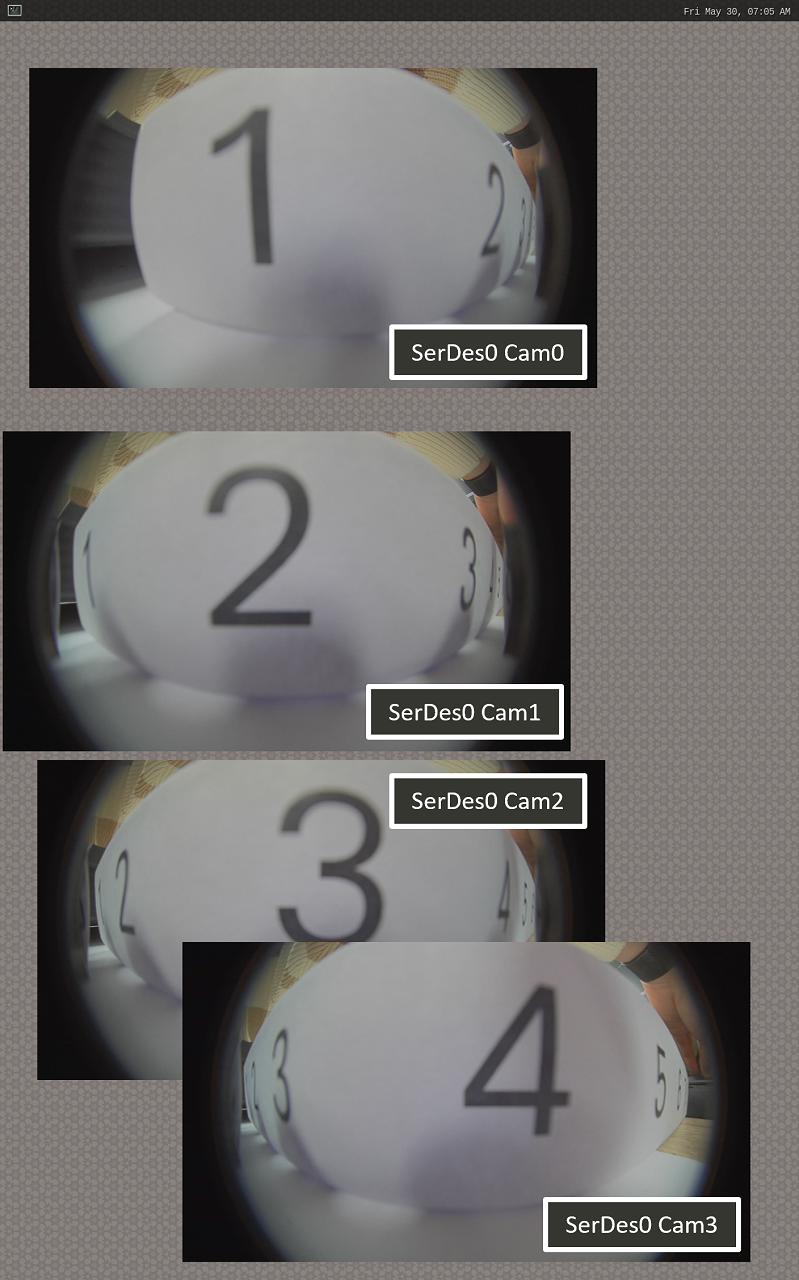
Show 4x SerDes streams on Weston
Note
To use MediaTek video codec and MDP hardware, users MUST load video.dtbo. For more details, please refer to Genio 720-EVK Video Codec.
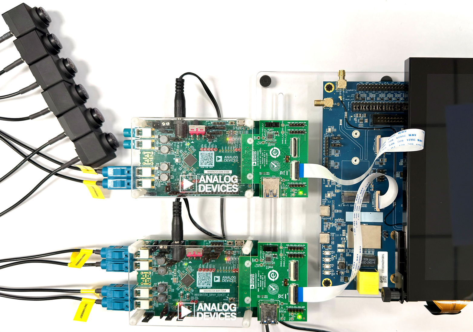
Dual ADI SerDes MAX96724 & ABEO AG190H
Hardware Setup
Prepare 2x CAM-DTB-D10 and 6x ABEO AG190H sensors
Connect the DTB to CAM0 and CAM1 slots

Software Setup
Select the dtbo
camera-ag190h-max96724-dual-std.dtbothroughgenio-flashgenio-flash --load-dtbo camera-ag190h-max96724-dual-std.dtboFind the media device of the camera system
export MEDIA_DEV=$(v4l2-ctl -z platform:$(basename `find /sys/bus/platform/devices/ -name "*seninf-top"`) --list-devices | grep media)
echo ${MEDIA_DEV}
/dev/media3
Set the media topology and the format on the EVK
# Set the name of MAX96724
MAX96724_1_NAME="max96724 7-0027:0"
MAX96724_2_NAME="max96724 8-0027:0"

# Set CAM0 pipeline
media-ctl -d ${MEDIA_DEV} -l "'${MAX96724_1_NAME}':0 -> 'seninf-0':0 [1]"
media-ctl -d ${MEDIA_DEV} -l "'seninf-0':1 -> '1a092000.camsv2':0 [1]"
media-ctl -d ${MEDIA_DEV} -l "'seninf-0':2 -> '1a093000.camsv3':0 [1]"
media-ctl -d ${MEDIA_DEV} -l "'seninf-0':3 -> '1a094000.camsv4':0 [1]"
media-ctl -d ${MEDIA_DEV} -l "'seninf-0':4 -> '1a095000.camsv5':0 [1]"

media-ctl -d ${MEDIA_DEV} -V "'${MAX96724_1_NAME}':0 [fmt:YUYV8_1X16/1920x1080]"
media-ctl -d ${MEDIA_DEV} -V "'seninf-0':1 [fmt:YUYV8_1X16/1920x1080]"
media-ctl -d ${MEDIA_DEV} -V "'seninf-0':2 [fmt:YUYV8_1X16/1920x1080]"
media-ctl -d ${MEDIA_DEV} -V "'seninf-0':3 [fmt:YUYV8_1X16/1920x1080]"
media-ctl -d ${MEDIA_DEV} -V "'seninf-0':4 [fmt:YUYV8_1X16/1920x1080]"
media-ctl -d ${MEDIA_DEV} -V "'1a092000.camsv2':1 [fmt:YUYV8_1X16/1920x1080]"
media-ctl -d ${MEDIA_DEV} -V "'1a093000.camsv3':1 [fmt:YUYV8_1X16/1920x1080]"
media-ctl -d ${MEDIA_DEV} -V "'1a094000.camsv4':1 [fmt:YUYV8_1X16/1920x1080]"
media-ctl -d ${MEDIA_DEV} -V "'1a095000.camsv5':1 [fmt:YUYV8_1X16/1920x1080]"

# Set CAM1 pipeline
media-ctl -d ${MEDIA_DEV} -l "'${MAX96724_2_NAME}':0 -> 'seninf-1':0 [1]"
media-ctl -d ${MEDIA_DEV} -l "'seninf-1':1 -> '1a096000.camsv6':0 [1]"
media-ctl -d ${MEDIA_DEV} -l "'seninf-1':2 -> '1a097000.camsv7':0 [1]"

media-ctl -d ${MEDIA_DEV} -V "'${MAX96724_2_NAME}':0 [fmt:YUYV8_1X16/1920x1080]"
media-ctl -d ${MEDIA_DEV} -V "'seninf-1':1 [fmt:YUYV8_1X16/1920x1080]"
media-ctl -d ${MEDIA_DEV} -V "'seninf-1':2 [fmt:YUYV8_1X16/1920x1080]"
media-ctl -d ${MEDIA_DEV} -V "'1a096000.camsv6':1 [fmt:YUYV8_1X16/1920x1080]"
media-ctl -d ${MEDIA_DEV} -V "'1a097000.camsv7':1 [fmt:YUYV8_1X16/1920x1080]"
Find the video device of the camera system
declare -a VIDEO_DEV=($(for i in `find /sys/bus/platform/devices/ -name "*camsv*" | sort`; do media-ctl -d ${MEDIA_DEV} --entity "`basename $i` video stream" ; done))
echo ${VIDEO_DEV[*]}
/dev/video5 /dev/video6 /dev/video7 /dev/video8 /dev/video9 /dev/video10
Launch dual ADI SerDes MAX96724 pipeline to show images on the Weston desktop
gst-launch-1.0 v4l2src device=${VIDEO_DEV[0]} ! video/x-raw,width=1920,height=1080,format=YUY2 ! v4l2convert output-io-mode=dmabuf-import ! video/x-raw,width=480,height=270 ! waylandsink sync=false &
gst-launch-1.0 v4l2src device=${VIDEO_DEV[1]} ! video/x-raw,width=1920,height=1080,format=YUY2 ! v4l2convert output-io-mode=dmabuf-import ! video/x-raw,width=480,height=270 ! waylandsink sync=false &
gst-launch-1.0 v4l2src device=${VIDEO_DEV[2]} ! video/x-raw,width=1920,height=1080,format=YUY2 ! v4l2convert output-io-mode=dmabuf-import ! video/x-raw,width=480,height=270 ! waylandsink sync=false &
gst-launch-1.0 v4l2src device=${VIDEO_DEV[3]} ! video/x-raw,width=1920,height=1080,format=YUY2 ! v4l2convert output-io-mode=dmabuf-import ! video/x-raw,width=480,height=270 ! waylandsink sync=false &
gst-launch-1.0 v4l2src device=${VIDEO_DEV[4]} ! video/x-raw,width=1920,height=1080,format=YUY2 ! v4l2convert output-io-mode=dmabuf-import ! video/x-raw,width=480,height=270 ! waylandsink sync=false &
gst-launch-1.0 v4l2src device=${VIDEO_DEV[5]} ! video/x-raw,width=1920,height=1080,format=YUY2 ! v4l2convert output-io-mode=dmabuf-import ! video/x-raw,width=480,height=270 ! waylandsink sync=false &
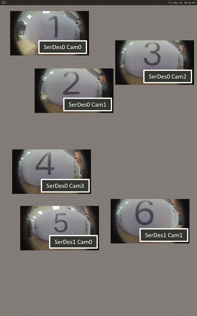
Show 6x SerDes streams on Weston