Genio 350-EVK
This page provides board-specific information on the display interfaces of the Genio 350-EVK board. For common display and compositor information, please visit the Display page.
Display Interfaces on Genio 350-EVK
There are three display interfaces on Genio 350-EVK:
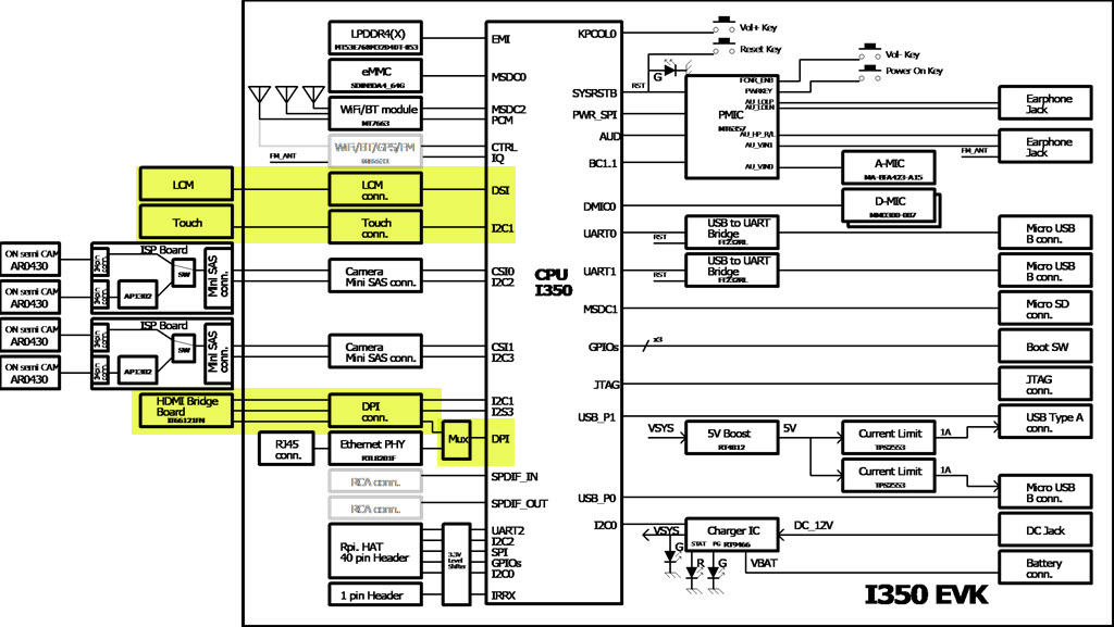
- HDMI port
The MT8365 SoC provides DPI display interface, and a DPI-to-HDMI bridge IC on the Genio 350-EVK provides HDMI display output.
The maximum supported resolution and refresh rate are
1920x1080@30Hz.The DPI interface is mutually exclusive to the Ethernet PHY due to SoC pin mux settings.
- MIPI-DSI port
StarTek LCM(KD070FHFID015-C021A) with touch panel is provided in the kit.
- LVDS port
The MT8365 SoC provides an LVDS interface.
The DPI interface is utilized to provide input to the LVDS encoder, and the LVDS encoder outputs through the MIPI port.
Both DSI and HDMI must be disabled when LVDS is enabled,
The Ethernet PHY could be enabled when LVDS is enabled.
Default rity-demo-image enables dual display DSI and HDMI. Other display combinations can be enabled by loading the device tree overlay during the flash programming process.
Lists of Display Device Tree Overlay
Starting from v25, none of the EVK default DTS files enable any display interfaces; loading the relevant DTBOs is required to enable them.
For the G700 EVK, the default configuration loads display-dsi.dtbo and display-hdmi.dtbo.
$ genio-flash -i rity-demo-image
    Genio Tools: v1.7.0a1
    Yocto Image:
    ...
    machine:  genio-350-evk
    overlays: ['video.dtbo', 'display-hdmi.dtbo', 'gpu-mali.dtbo', 'display-dsi.dtbo']
If you do not need display-dsi.dtbo, use the unload-dtbo option to remove the default display-dsi.dtbo
$ genio-flash -i rity-demo-image --unload-dtbo display-dsi.dtbo
    Genio Tools: v1.7.0a1
    Yocto Image:
    ...
    machine:  genio-350-evk
    overlays: ['display-hdmi.dtbo', 'video.dtbo', 'apusys.dtbo']
Here are lists of all available display combination device tree overlays and description link of each one:
dtbo |
Description |
|---|---|
|
dtbo |
Description |
|---|---|
No need dtbo |
dtbo |
Description |
|---|---|
|
|
|
|
|
DSI + HDMI
DSI + HDMI are the default dual display interfaces for the prebuilt rity-demo-image.
Flash the board with:
$ genio-flash -i rity-demo-image
    Genio Tools: v1.7.0a1
    Yocto Image:
    ...
    machine:  genio-350-evk
    overlays: ['display-dsi.dtbo', 'apusys.dtbo', 'display-hdmi.dtbo', 'video.dtbo']
As shown in the example above, both display-dsi.dtbo and display-hdmi.dtbo are loaded by default.
After boot into the console you can use modeprint mediatek command to check if both DSI and HDMI ports have been properly configured:
root@genio-350-evk:~# modeprint mediatek
Starting test
Resources

count_connectors : 2
count_encoders   : 2
count_crtcs      : 2
count_fbs        : 0

Connector: HDMI-A-1
        id             : 32
        encoder id     : 31
        conn           : connected
        size           : 600x340 (mm)
        count_modes    : 13
        count_props    : 5
        props          : 1 2 5 6 4
        count_encoders : 1
        encoders       : 31
Mode: "1280x720" 1280x720 60
    ...
Connector: DSI-1
        id             : 34
        encoder id     : 33
        conn           : connected
        size           : 95x151 (mm)
        count_modes    : 1
        count_props    : 5
        props          : 1 2 5 6 4
        count_encoders : 1
        encoders       : 33
Mode: "1200x1920" 1200x1920 60
The associated display data pipeline can process up to 1920x1200 with 60Hz refresh rate for DSI, and 1920x1080 with 30Hz refresh rate for HDMI.
Headless
Headless means that Yocto works without enabling any physical display connector.
There is a virtual display at /dev/dri/renderD128 prepared for offline rendering.
To enable Headless, unload the overlay file display-dsi.dtbo and display-hdmi.dtbo during flashing process:
genio-flash -i rity-demo-image --unload-dtbo display-dsi.dtbo --unload-dtbo display-hdmi.dtbo
If you don’t want to re-flash the entire root file system, you can simply update the overlay configuration with:
genio-flash -i rity-demo-image --unload-dtbo display-dsi.dtbo --unload-dtbo display-hdmi.dtbo kernel mmc0boot1
After boot into the console you will see the following error log which is because there is no physical display for Weston desktop rendering:
[FAILED] Failed to start Weston, a compositor, as a system service.
See 'systemctl status weston.service' for details.
You can use modeprint mediatek command to check if headless has been properly configured by checking if connector count equals 0:
root@genio-350-evk:~# modeprint mediatek
Starting test
Resources

count_connectors : 0
count_encoders   : 0
DSI
To enable DSI0 as the only display connector, unload the overlay file display-hdmi.dtbo during flashing process:
genio-flash -i rity-demo-image --unload-dtbo display-hdmi.dtbo
If you don’t want to re-flash the entire root file system, you can simply update the overlay configuration with:
genio-flash -i rity-demo-image --unload-dtbo display-hdmi.dtbo kernel mmc0boot1
After boot into the console you can use modeprint mediatek command to check if DSI port have been properly configured:
root@genio-350-evk:~# modeprint mediatek
Starting test
Resources

count_connectors : 1
count_encoders   : 1
count_crtcs      : 1
count_fbs        : 0

Connector: DSI-1
        id             : 32
        encoder id     : 31
        conn           : connected
        size           : 95x151 (mm)
        count_modes    : 1
        count_props    : 5
        props          : 1 2 5 6 4
        count_encoders : 1
        encoders       : 31
Mode: "1200x1920" 1200x1920 60
The associated display data pipeline can process up to 1920x1200 with 60Hz refresh rate for DSI.
HDMI
To enable HDMI as the only display connector, unload the overlay file display-dsi.dtbo during flashing process:
genio-flash -i rity-demo-image --unload-dtbo display-dsi.dtbo
If you don’t want to re-flash the entire root file system, you can simply update the overlay configuration with:
genio-flash -i rity-demo-image --unload-dtbo display-dsi.dtbo kernel mmc0boot1
After boot into the console you can use modeprint mediatek command to check if HDMI port have been properly configured:
root@genio-350-evk:~# modeprint mediatek
Starting test
Resources

count_connectors : 1
count_encoders   : 1
count_crtcs      : 2
count_fbs        : 0

Connector: HDMI-A-1
        id             : 32
        encoder id     : 31
        conn           : connected
        size           : 600x340 (mm)
        count_modes    : 13
        count_props    : 5
        props          : 1 2 5 6 4
        count_encoders : 1
        encoders       : 31
Mode: "1280x720" 1280x720 60
Mode: "1280x720" 1280x720 60
...
The associated display data pipeline can process up to 1920x1080 with 30Hz refresh rate for HDMI.
LVDS
To enable LVDS as the only display connector, load the overlay file display-lvds.dtbo during flashing process:
genio-flash -i rity-demo-image --unload-dtbo display-dsi.dtbo --unload-dtbo display-hdmi.dtbo --load-dtbo display-lvds.dtbo
If you don’t want to re-flash the entire root file system, you can simply update the overlay configuration with:
genio-flash -i rity-demo-image --unload-dtbo display-dsi.dtbo --unload-dtbo display-hdmi.dtbo --load-dtbo display-lvds.dtbo kernel mmc0boot1
After boot into the console you can use modeprint mediatek command to check if LVDS port have been properly configured:
root@genio-350-evk:~# modeprint mediatek
Starting test
Resources

count_connectors : 1
count_encoders   : 1
count_crtcs      : 2
count_fbs        : 0

Connector: LVDS-1
        id             : 32
        encoder id     : 31
        conn           : connected
        size           : 344x193 (mm)
        count_modes    : 1
        count_props    : 5
        props          : 1 2 5 6 4
        count_encoders : 1
        encoders       : 31
Mode: "1366x768" 1366x768 60
The associated display data pipeline can process up to 1366x768 with 60Hz refresh rate for LVDS.
HDMI on Genio 350-EVK
To use the HDMI port on Genio 350-EVK, you need to:
Set the boot switch (
SW2101) to ON=HDMI, as shown below: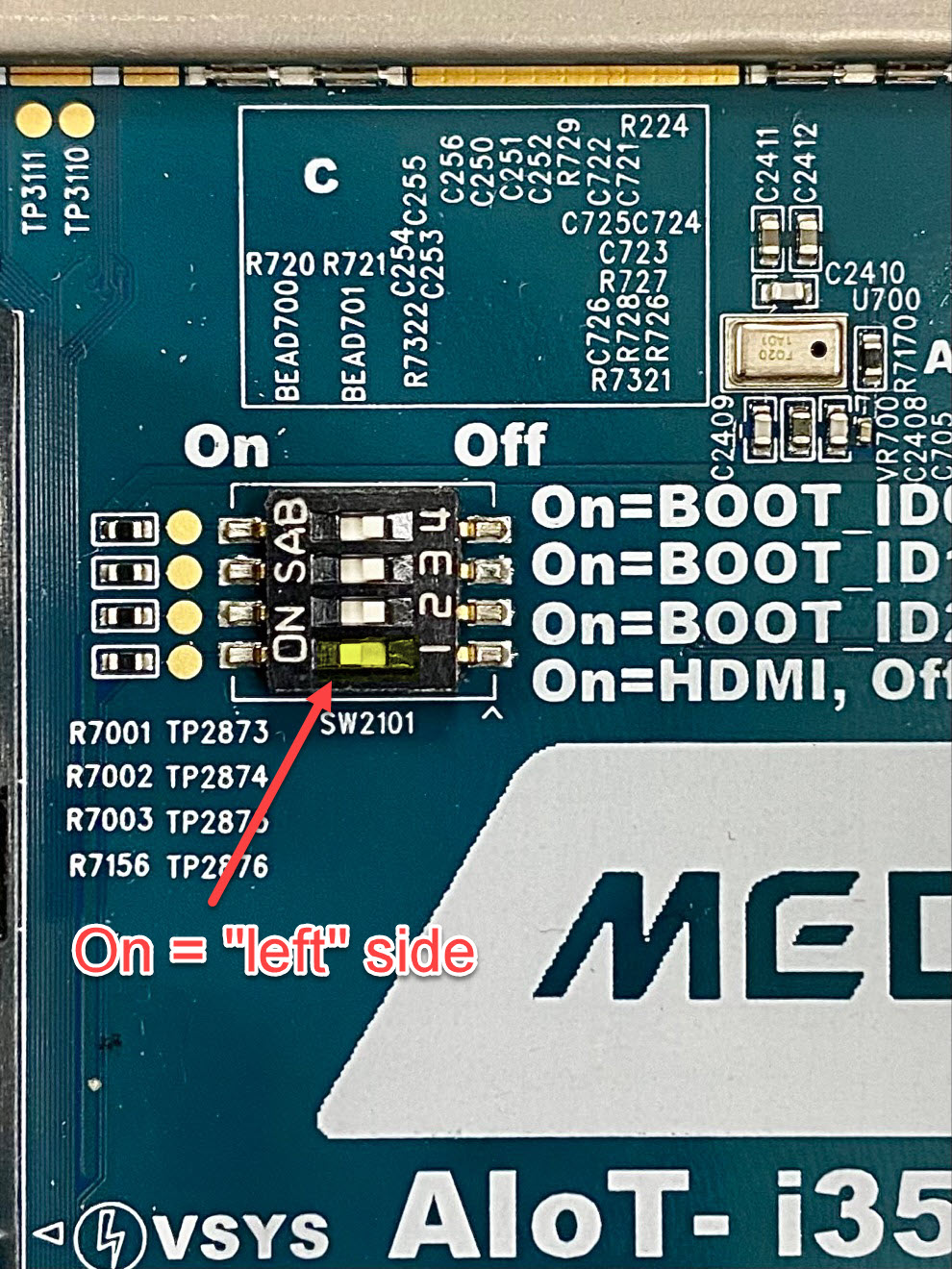
If you use a P1V3 EVK, make sure to short all four jumpers (
J2324, J2325, J2326, J2327) at the upper left corner: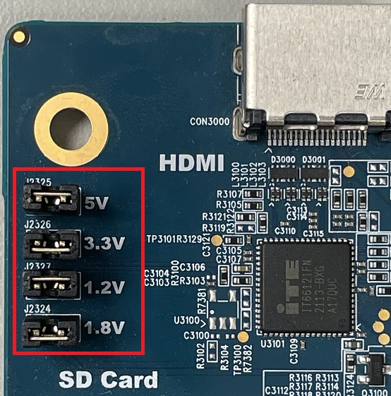
Note
Open all four jumpers when Ethernet is used.
Flash rity-demo-image. In addition,
Make sure you don’t add the
--load-dtbo net-ethernet.dtboparameter. If you load thenet-ethernet.dtbooverlay, it disables the HDMI port.If you’ve enabled DSI panel using default rity-demo-image or kernel configuration, you must attach the LCM panel as described in the DSI LCM section below.
Connect to HDMI monitors to the main board before power-on.
Power on or reset the main board.
Note
Genio 350-EVK does not support Full HD (1920x1080@60Hz). If your HDMI monitor does not support 1920x1080@30Hz, it is likely to use 720p resolution, depending on the capability of your monitor.
If the HDMI monitor is successfully detected, it shows a desktop by default, and you may check the log of weston compositor with:
cat /var/log/weston.log
If the HDMI monitor is successfully detected, it would have log similar to the following, although the exact detected resolution list depends on the actual monitor:
[10:44:03.533] DRM: head 'HDMI-A-1' found, connector 32 is connected, EDID make 'BNQ', model 'BenQ PD3200U', serial '87M00693019'
[10:44:03.533] DRM: head 'DSI-1' found, connector 34 is connected, EDID make 'unknown', model 'unknown', serial 'unknown'
[10:44:03.534] Registered plugin API 'weston_drm_output_api_v1' of size 24
[10:44:03.534] Chosen EGL config details: id:   1 rgba: 8 8 8 0 buf: 24 dep:  0 stcl: 0 int: 0-0 type: win|pbf|swap_preserved vis_id: XRGB8888 (0x34325258)
[10:44:03.535] Output HDMI-A-1 (crtc 45) video modes:
            1920x1080@30.0 16:9, current, 74.2 MHz
            1920x1080@25.0 16:9, 74.2 MHz
            1920x1080@24.0 16:9, 74.2 MHz
            1280x800@59.9, 71.0 MHz
            1280x720@60.0, 74.2 MHz
            1280x720@60.0 16:9, 74.2 MHz
            1280x720@59.9 16:9, 74.2 MHz
            1280x720@50.0 16:9, 74.2 MHz
            1024x768@60.0, 65.0 MHz
            832x624@74.6, 57.3 MHz
            800x600@75.0, 49.5 MHz
            800x600@60.3, 40.0 MHz
            720x576@50.0 16:9, 27.0 MHz
            720x480@60.0 16:9, 27.0 MHz
            720x480@59.9 16:9, 27.0 MHz
            640x480@75.0, 31.5 MHz
            640x480@60.0 4:3, 25.2 MHz
            640x480@59.9, 25.2 MHz
            640x480@59.9 4:3, 25.2 MHz
            720x400@70.1, 28.3 MHz
[10:44:03.535] associating input device event0 with output HDMI-A-1 (none by udev)
[10:44:03.535] associating input device event1 with output HDMI-A-1 (none by udev)
[10:44:03.535] Output 'HDMI-A-1' enabled with head(s) HDMI-A-1
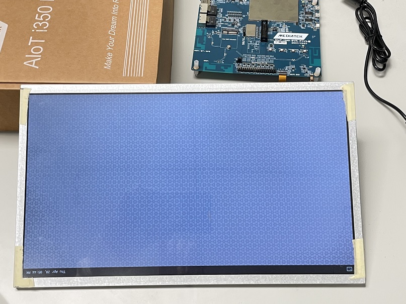
MIPI-DSI LCM on Genio 350-EVK
Please follow the steps below to connect to the StarTek LCM(KD070FHFID015-C021A) provided in the evaluation kit.
LCM Setup on Genio 350-EVK
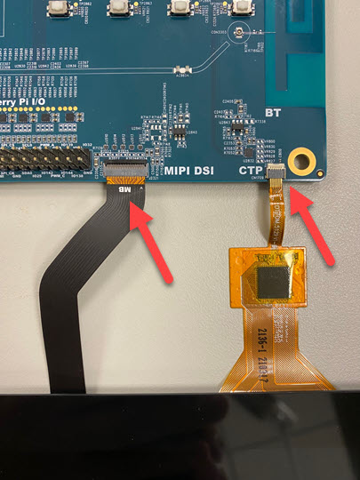
Please connect LCM FPC as shown below:
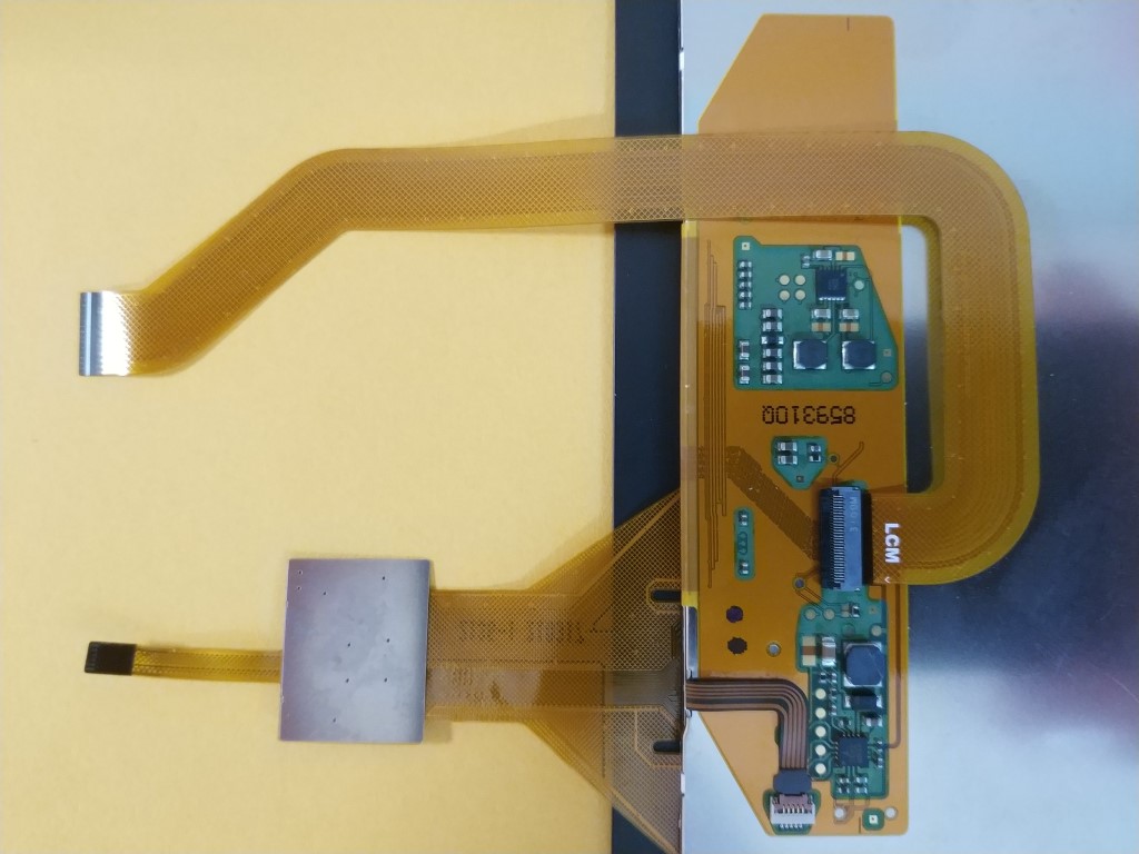
and then connect the FPC to the main board with the label MB facing upward:
LVDS on Genio 350-EVK
The prebuilt rity-demo-image supports MIPI output LVDS, which can be connected to the LVDS to LVDS Daughter Board, and then to the panel AUO G156XTN01.0.
Note
The LVDS to LVDS Daughter Board does not come with the Genio 350-EVK set. Please contact MTK CPM to obtain one.
The LVDS to LVDS Daughter Board does not contain any bridge ICs. It only transfer LVDS signals between the MIPI output to the panel connector.
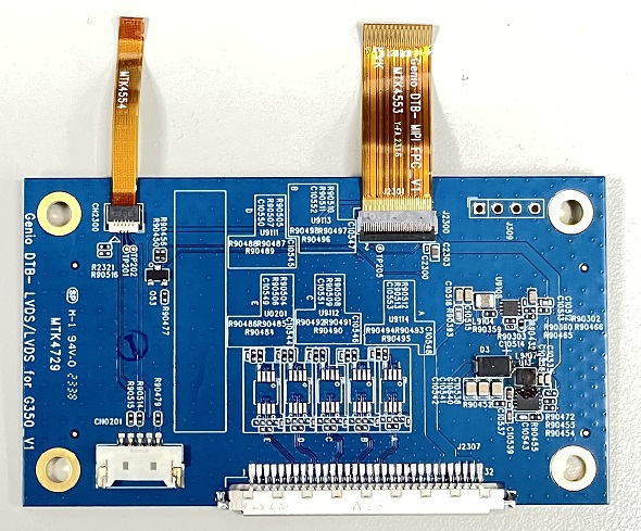
LVDS Setup on Genio 350-EVK
An example of the daughter board is shown below:
To install the daughter board, turn the daughter board to the back side, then connect the MIPI and CTP cables with those on the daughter board.
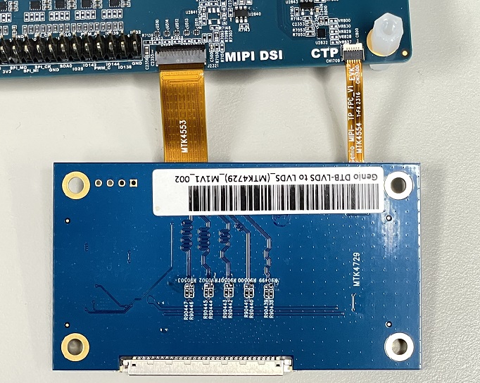
Connect the LVDS cables to both the daughter board and the panel.
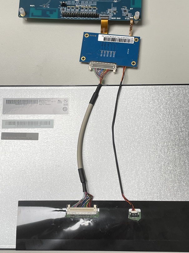
A complete setup example is provided below.
Troubleshooting
HDMI Does Not Work on Genio 350-EVK
Please kindly check the following:
Please check the HDMI/Ethernet switch on the board.
Please check the HDMI/Ethernet jumpers on the board.
Please make sure Ethernet is not enabled in the dtbo
If you’ve enabled DSI panel in the dtbo or kernel configuration, you MUST attach the DSI panel hardware.