YUV Sensor
Camera Package And Specification
The YUV camera DTB for Genio 1200-EVK is CAM DTB-D6.
It contains Onsemi AP1302 ISP and AR0830 Sensor.
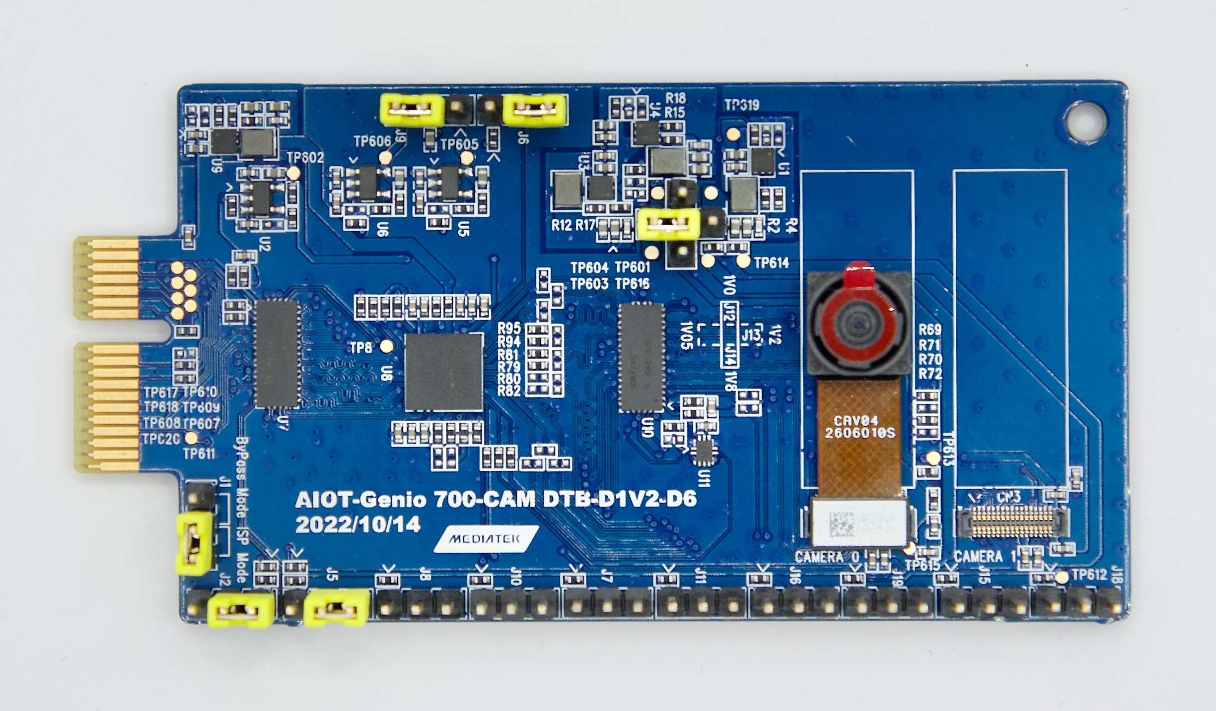
Camera DTB D6 - Onsemi AP1302 ISP and AR0830 Sensor
Connect The Camera To The EVK
There are 3 MIPI-CSI sockets on Genio 1200-EVK, which are CSI0, CSI1, and CSI2.
In the following figure, the camera DTB is connected to the CSI0 socket.
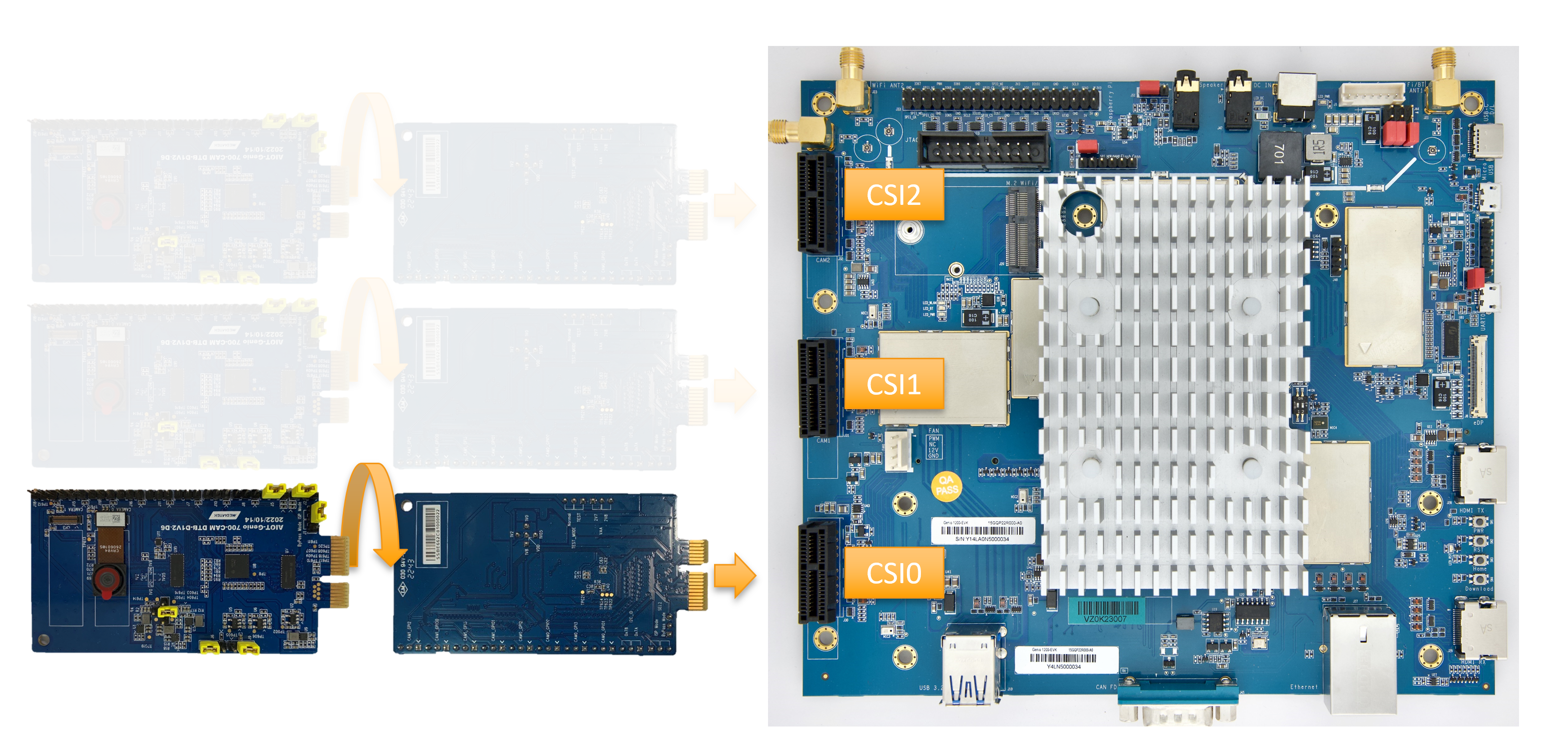
Connect Camera DTB D6 to Genio 1200-EVK (Schematic)
The hardware connection is AR0830 ---> AP1302 ---> MIPI-CSI On EVK.
The camera daughter board can be configured in ISP mode and Bypass mode.
In ISP mode, the images from the AR0830 camera module are passed to AP1302 ISP before being received by the EVK.
In Bypass mode, the images from the AR0830 camera module are transferred to the EVK directly.
By default, IoT Yocto only supports ISP mode.
First, configure camera DTB to ISP mode. You will need 6 jumpers and 1 camera sensor configured as the below figure. Make sure you have the correct jumper setting and that the camera sensor is properly connected to the CAMERA 0 slot.
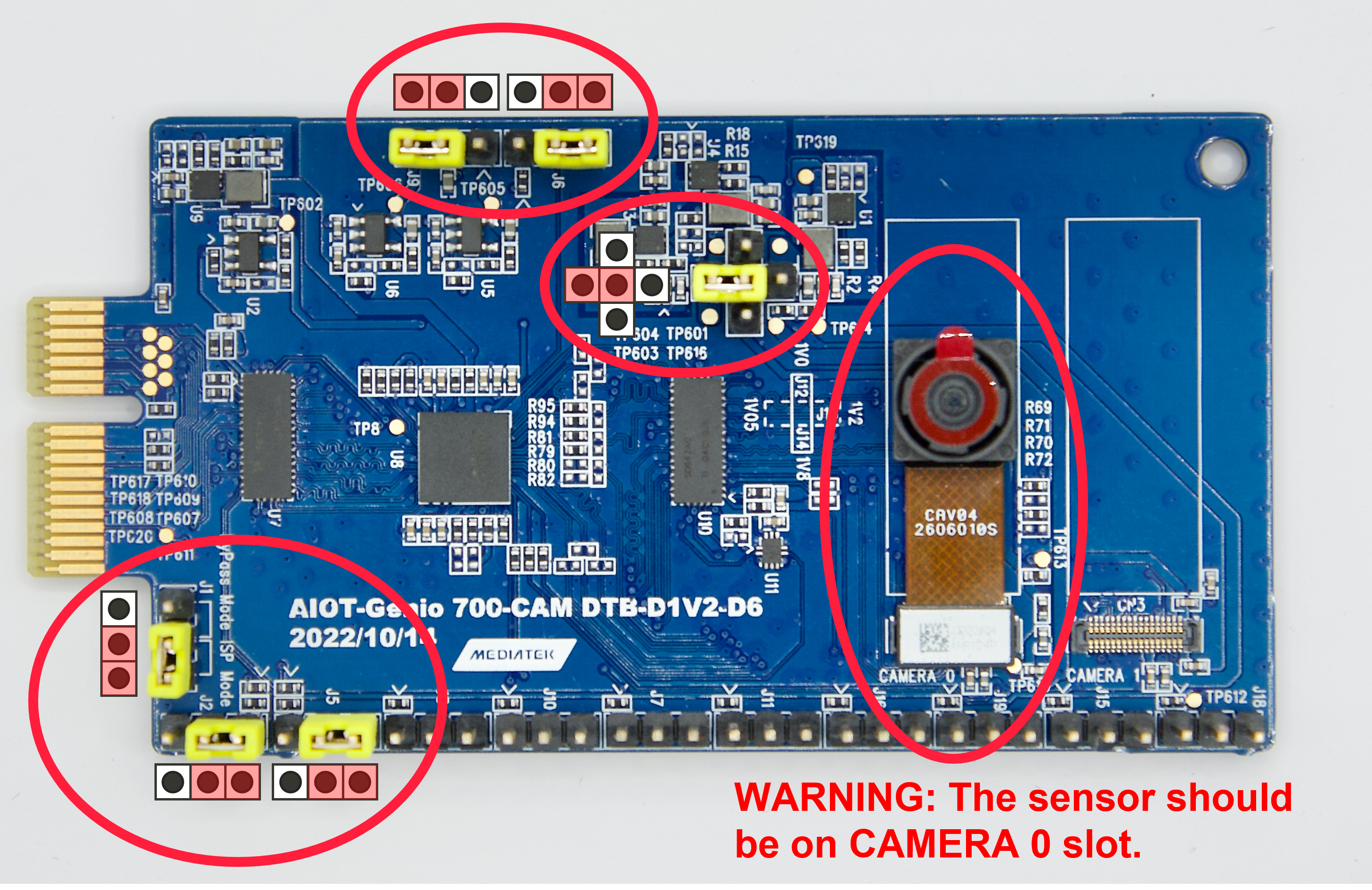
Camera DTB D6 - ISP mode
Second, connect the camera DTB to the MIPI-CSI socket.
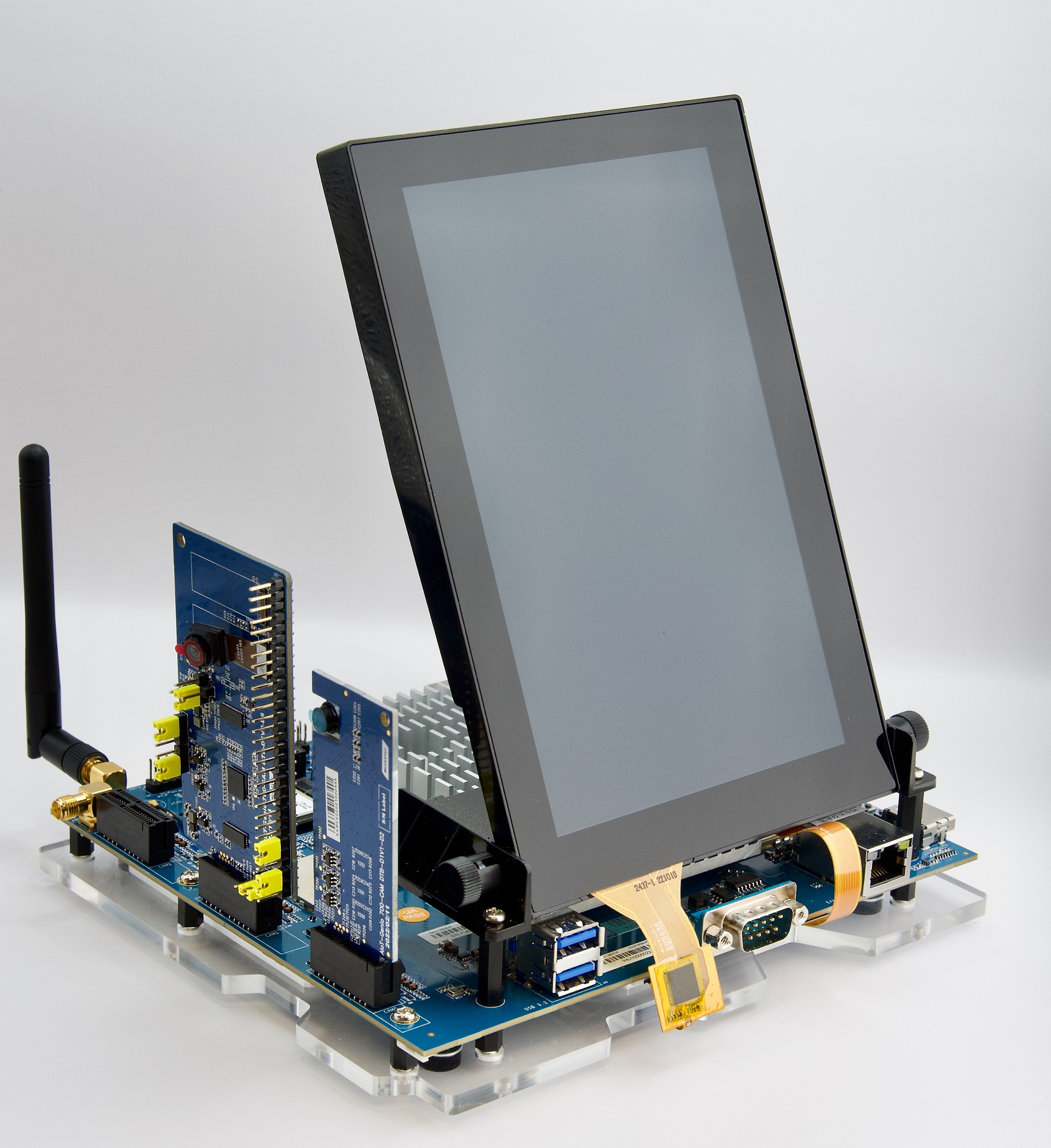
Connect Camera DTB D6 to Genio 1200-EVK (Entity)
Note
All three MIPI-CSI sockets are available. The user can connect the camera sensor to any socket.
After finishing the above steps, the hardware connection is complete.
Warning
Please make sure all the above settings, including the jumpers, and camera slot, and MIPI-CSI socket, are correct. Otherwise, the I2C connection between the sensor, ISP, and SoC will fail.
MediaTek Imgsensor Architecture
Note
All command operations presented in this chapter are based on the IoT Yocto v23.1, Genio 1200-EVK and Onsemi AP1302 ISP and AR0830 sensor. You might get the different operation result depending on the platform you use.
Select Camera Device Tree Blob Overlay (Imgsensor)
The camera device is inactive by default, so the kernel has to load a specific device tree blob overlay to enable it. Please refer to bl33u-boot for more details.
Platform |
Camera DTBO |
Description |
|---|---|---|
Genio 1200-EVK |
camera-ar0830-ap1302-2lanes-csi0.dtbo |
CAM-DTB-D6 w/ Onsemi AR0830 sensor, connected to CSI0, use 2-lane MIPI CSI |
Genio 1200-EVK |
camera-ar0830-ap1302-csi0.dtbo |
CAM-DTB-D6 w/ Onsemi AR0830 sensor, connected to CSI0, use 4-lane MIPI CSI |
Genio 1200-EVK |
camera-ar0830-ap1302-csi1.dtbo |
CAM-DTB-D6 w/ Onsemi AR0830 sensor, connected to CSI1, use 4-lane MIPI CSI |
Genio 1200-EVK |
camera-ar0830-ap1302-csi2.dtbo |
CAM-DTB-D6 w/ Onsemi AR0830 sensor, connected to CSI2, use 4-lane MIPI CSI |
genio-flash --list-dtbo
List of available DTBO:
- camera-ar0830-ap1302-2lanes-csi0.dtbo
- camera-ar0830-ap1302-csi0.dtbo
- camera-ar0830-ap1302-csi1.dtbo
- camera-ar0830-ap1302-csi2.dtbo
- ...
genio-flash --load-dtbo camera-ar0830-ap1302-csi0.dtbo --load-dtbo gpu-mali.dtbo --load-dtbo apusys.dtbo --load-dtbo video.dtbo
Warning
Please select the DTBO according to the CSI slot to which the camera sensor is connected.
For example, if the camera is connected to the CSI0 slot, please load the dtbo camera-ar0830-ap1302-csi0.dtbo.
Otherwise, the camera initialization will fail.
Supported Formats And Sizes (Imgsensor)
Platform |
Sensor |
Stream Type |
Size |
Framerate |
Format |
MIPI Lanes |
|---|---|---|---|---|---|---|
Genio 1200-EVK |
Onsemi AP1302 & AR0830 |
Preview |
1920x1080 |
30 |
UYVY |
4 |
Genio 1200-EVK |
Onsemi AP1302 & AR0830 |
Preview |
2560x1440 |
30 |
UYVY |
4 |
Genio 1200-EVK |
Onsemi AP1302 & AR0830 |
Preview |
3840x2160 |
24 |
UYVY |
4 |
Genio 1200-EVK |
Onsemi AP1302 & AR0830 |
Preview |
1920x1080 |
30 |
UYVY |
2 |
Genio 1200-EVK |
Onsemi AP1302 & AR0830 |
Preview |
2560x1440 |
30 |
UYVY |
2 |
Genio 1200-EVK |
Onsemi AP1302 & AR0830 |
Preview |
3840x2160 |
12 |
UYVY |
2 |
Note
The supported format, resoulution, and framerate are related to the capability of the sensor and SoC.
V4L2 Device Node (Imgsensor)
Camera ISP is a complicated feature that has a large number of device nodes. The camera ISP driver creates 123 video devices in total.
MTK-ISP-DIP-V4L2has 68 devicesmtk-camhas 54 devicesmtk-v4l2-camerahas 1 device
MTK-ISP-DIP-V4L2 and mtk-cam are used by the camera ISP middleware.
The user can just focus on mtk-v4l2-camera which is for streaming.
v4l2-ctl --list-devices
...
MTK-ISP-DIP-V4L2 (platform:15000000.imgsys_fw):
(68 video devices)
/dev/media0
mtk-cam (platform:16000000.camisp):
(54 video devices)
/dev/media2
mtk-v4l2-camera (platform:mtkcam0):
/dev/video74
Launch Camera (Imgsensor)
The V4L2 nodes with the name mtk-v4l2-camera can be used for streaming.
For the YUV sensor, there’s only 1 V4L2 device which is for the preview stream.
The user can find the devices by the following command:
v4l2-ctl --list-device
mtk-v4l2-camera (platform:mtkcam0):
        /dev/video74
cat /sys/class/video4linux/video74/name
mtk-v4l2-camera@0-Preview
Important
The above v4l2 device node number is for example. The node number may change every time the system boots.
To quickly fetch the correct node and assign the environment variable:
declare -a video=(`v4l2-ctl --list-devices | grep mtk-v4l2-camera -A 1 | grep video | tr -d "\n"`)
printf "Preview Node\t= ${video[0]}\n"
Preview Node    = /dev/video74
Section Supported formats and Sizes (Imgsensor) shows the supported formats and sizes.
The user can also use the v4l2 utility, v4l2-ctl, to list formats.
v4l2-ctl -d ${video[0]} --list-formats-ext
ioctl: VIDIOC_ENUM_FMT
        Type: Video Capture Multiplanar

        [0]: 'UYVY' (UYVY 4:2:2)
                Size: Discrete 1920x1080
                        Interval: Discrete 0.033s (30.000 fps)
        ...
To launch the camera, the user can use v4l2-ctl, gst-launch-1.0, or other V4L2 applications.
Use
v4l2-ctlv4l2-ctl -d ${video[0]} --set-fmt-video=width=1920,height=1080,pixelformat=UYVY --stream-mmap --stream-count=10 --stream-to=/tmp/ap1302.yuv --verboseUse
gst-launch-1.0gst-launch-1.0 v4l2src device=${video[0]} ! video/x-raw,width=1920,height=1080,format=UYVY ! v4l2convert output-io-mode=dmabuf-import ! video/x-raw,width=1280,height=720 ! waylandsink sync=false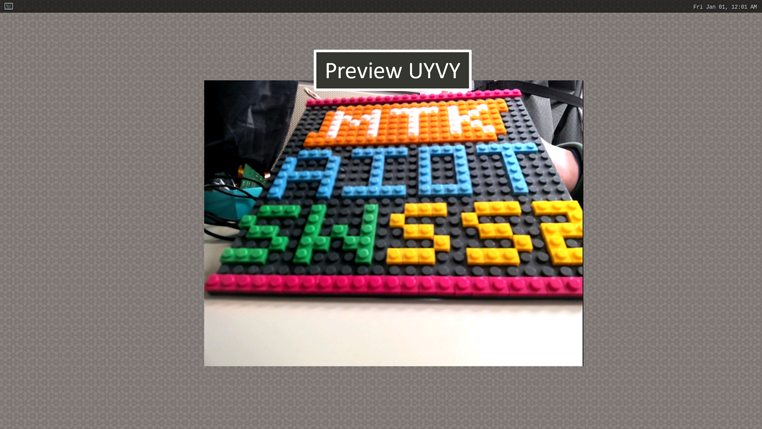
Show Preview stream on Weston
Note
To use MediaTek video codec and mdp hardware, the user needs to load video.dtbo. For more details, please refer to Genio 1200-EVK Video Codec.
Sensor Launch Time
In our camera operation sequence, we follow the steps below:
Open Camera
Power on the sensor
Release the reset pin
Configure the sensor settings
Stream on the sensor
Close Camera
Stream off the sensor
Hold the reset pin
Power off the sensor
When using the AP1302 ISP, it is necessary to download a specific firmware binary during initialization. The launch time of the camera depends on the size of the binary file. The log provided below illustrates the start-up process of the AP1302 ISP and displays the corresponding launch time.

The presented log provides an overview of the AP1302 ISP start-up process and focuses on the launch time, which primarily measures the duration it takes to transmit the firmware through I2C at a speed of 400KHz.
Camera Integration (Imgsensor)
The user who wants to use other sensors will need to integrate the sensor driver into MediaTek Imgsensor. For more details, please refer to the sensor porting guide on MediaTek On-Line:
Sensor Type |
Document Path |
|---|---|
RAW |
IoT/Software/Genio Series SoC/Genio 1200/IoT Yocto/Camera/MTK_MT8395_IoT_Yocto_RAW_Image_Sensor_Driver_Development_Guide_v1.4.docx |
YUV |
IoT/Software/Genio Series SoC/Genio 1200/IoT Yocto/Camera/MTK_MT8395_IoT_Yocto_YUV_Image_Sensor_Driver_Development_Guide_v1.4.docx |
V4L2 Sensor Architecture
Note
All command operations presented in this chapter are based on the IoT Yocto v23.2, Genio 1200-EVK and Onsemi AP1302 ISP and AR0830 sensor. You might get different operation results depending on the platform you use.
Select Camera Device Tree Blob Overlay (V4L2 Sensor)
The camera device is inactive by default, so the kernel has to load a specific device tree blob overlay to enable it. Please refer to bl33u-boot for more details.
Platform |
Camera DTBO |
Description |
|---|---|---|
Genio 1200-EVK |
camera-ar0830-ap1302-csi0-std.dtbo |
CAM-DTB-D6 w/ Onsemi AR0830 sensor, connected to CSI0, use 4-lane MIPI CSI and standard V4L2 sensor driver |
Genio 1200-EVK |
camera-it6510-csi0-std.dtbo |
Genio DTB-DP to MIPI w/ ITE IT6510FN bridge, connected to CSI0, use 4-lane MIPI CSI and standard V4L2 sensor driver |
genio-flash --list-dtbo
List of available DTBO:
        - camera-ar0830-ap1302-csi0-std.dtbo
        - camera-it6510-csi0-std.dtbo
        - ...
genio-flash --load-dtbo camera-ar0830-ap1302-csi0-std.dtbo --load-dtbo gpu-mali.dtbo --load-dtbo apusys.dtbo --load-dtbo video.dtbo
Supported Formats And Sizes (V4L2 Sensor)
The array of supported formats and sizes depends on the two primary aspects:
The capabilities of the sensor and the corresponding driver implementation.
The capabilities of the SoC (System on a Chip) and the corresponding driver implementation.
A couple of examples would further explain this:
An external ISP (Image Signal Processor) such as the Onsemi AP1302 can scale the size of sensor images up to a size of 13MP. It can then export these images in some formats, including YUV422, YUV420, RGB888, etc. However, the SoC can only accept the YUV422-8bit format and can process images up to 16MP in size. It is also crucial to consider other influential factors such as the throughput of the MIPI C/D-PHY data lane.
The ITE IT6510 is a bridge IC converting the input from a DP signal into MIPI CSI (Video) and I2S (Audio) signals. It can support up to a FHD@120Hz, 4K@30Hz DP signal, but the signal is also somewhat dependent on the DP signal source. The sizes reported by the IT6510 driver are from the IT6510 hardware, which also represents the size of the DP source.
The degree of flexibility for setting the format and the size is subject to the sensor design and the driver implementation. Some sensors (e.g., ITE IT6510) provide a fixed set of formats and sizes, while some (e.g., Onsemi AP1302) can scale up/down the size in a wide range. Regardless of how the sensor determines its format and size, if the SoC supports those specifications, the user can set the SoC through the standard V4L2 interface and obtain the images from the video device node.
V4L2 Device Node (V4L2 Sensor)
The video node is the interface for users to obtain the images. On Genio 1200-EVK, they are called mtk-cam camsv-* main-stream.
The media-ctl is a useful tool to list video devices.
declare -a video=(`for i in {0..5}; do media-ctl -d /dev/media0 --entity "mtk-cam camsv-$i main-stream"; done | tr "\n" " "`)
echo ${video[*]}
/dev/video53 /dev/video54 /dev/video55 /dev/video56 /dev/video57 /dev/video58
Warning
The assigned node number for the video device may vary depending on the sequence of the probing process during the boot-up phase. As such, it is crucial to ensure the accuracy of the video device node before using the camera.
Launch Camera (V4L2 Sensor)
The initial step is to link all the necessary components within the media device. The structure of the YUV camera pipeline is quite straightforward. It fundamentally incorporates only three components: the sensor, SENINF, and CAMSV.
media-ctl -d /dev/media0 -l "'seninf-0':1 -> 'mtk-cam camsv-0':0 [5]"
media-ctl -d /dev/media0 -l "'ap1302.1-003c':2 -> 'seninf-0':0 [1]"
The second step is to assign the correct format and size to each component incorporated in the camera pipeline.
media-ctl -d /dev/media0 -V "'ap1302.1-003c':2 [fmt:UYVY8_1X16/1920x1080 field:none]"
media-ctl -d /dev/media0 -V "'seninf-0':1 [fmt:UYVY8_1X16/1920x1080 field:none]"
media-ctl -d /dev/media0 -V "'mtk-cam camsv-0':1 [fmt:UYVY8_1X16/1920x1080 field:none]"
For the third step, it’s necessary to identify the correct video device node. For further information on this, please refer to V4L2 Device Node (V4L2 Sensor).
declare -a video=(`for i in {0..5}; do media-ctl -d /dev/media0 --entity "mtk-cam camsv-$i main-stream"; done | tr "\n" " "`)
echo ${video[*]}
/dev/video53 /dev/video54 /dev/video55 /dev/video56 /dev/video57 /dev/video58
Important
You have to select the video node that corresponds to the CAMSV instance linked in the second step.
In this given example, mtk-cam camsv-0 is the linked instance, hence the video device node should be ${video[0]} or /dev/video53.
Lastly, to activate the camera, the user can use v4l2-ctl, gst-launch-1.0, or other V4L2 applications.
Use
v4l2-ctlv4l2-ctl -d ${video[0]} --set-fmt-video=width=1920,height=1080,pixelformat=UYVY --stream-mmap --stream-count=10 --stream-to=/tmp/ap1302.yuv --verboseUse
gst-launch-1.0gst-launch-1.0 v4l2src device=${video[0]} ! video/x-raw,width=1920,height=1080,format=UYVY ! v4l2convert output-io-mode=dmabuf-import ! video/x-raw,width=1280,height=720 ! waylandsink sync=false
Note
To use MediaTek video codec and MDP hardware, the user needs to load video.dtbo. For more details, please refer to Genio 1200-EVK Video Codec.
Camera Integration (V4L2 Sensor)
In this section, we will demonstrate how to integrate a new sensor into Genio 1200-EVK.
1. Sensor Driver Enablement
The sensor driver should follow the Video 4 Linux 2 framework and function as a V4L2 sub-device. The implementation of the driver should include the necessary sub-device callbacks and the media entity initialization For more details, please refer to V4L2 sub-devices.
For the in-tree sensor driver, the kernel driver configuration can be set in meta-mediatek-bsp/recipes-kernel/linux/linux-mtk/mt8395-evk.cfg.
Set the config to y (built-in) or m (module)
CONFIG_VIDEO_AP1302=m
2. Device Tree Configuration
The device tree configuration is the most important part of the porting progress because it defines the sensor properties and the connection between the sensor and the SoC.
Adding the device tree node for the sensor as an out-of-tree DTBO is advised because the SoC’s camera-related dependencies are maintained as out-of-tree modules.
If you add the sensor-related device tree node directly into the in-tree Linux kernel, you may encounter errors indicating that the dependencies cannot be found.
To begin, copying the configuration from meta-mediatek-bsp/recipes-kernel/dtbo/genio-1200-evk/camera-ar0830-ap1302-csi0-std.dts is a good starting point.
The device tree configuration heavily relies on the design of the camera daughterboard and the related circuit, so the user has to modify the dtbo according to the hardware design.
For example, Genio 1200-EVK has pre-defined the pin usages for power, clock, reset, control, and data transmission.
For the pin definition of camea socket Genio 1200-EVK, please refer to Camera Pin Definition.
Fragment 4 defines the pins for the power-related control. The setting includes the electrical characteristics, the GPIO pin used, etc.
fragment@4 {
target-path = "/";
__overlay__ {
cam0_pdn: cam0-pdn-regulator {
compatible = "regulator-fixed";
regulator-name = "cam0_pdn";
regulator-min-microvolt = <1800000>;`
regulator-max-microvolt = <1800000>;
gpio = <&pio 54 0>;
startup-delay-us = <18000>;
enable-active-high;
};
cam0_avdd_en: cam0-avdd-en-regulator {
compatible = "regulator-fixed";
regulator-name = "cam0_avdd_en";
regulator-min-microvolt = <1800000>;
regulator-max-microvolt = <1800000>;
gpio = <&pio 56 0>;
startup-delay-us = <18000>;
enable-active-high;
regulator-always-on;
pinctrl-names = "default";
pinctrl-0 = <&cam0_avdd_en_pins>;
};
cam1_dvdd_en: cam1-dvdd-en-regulator {
compatible = "regulator-fixed";
regulator-name = "cam1_dvdd_en";
regulator-min-microvolt = <1800000>;
regulator-max-microvolt = <1800000>;
gpio = <&pio 58 0>;
startup-delay-us = <18000>;
enable-active-high;
regulator-always-on;
pinctrl-names = "default";
pinctrl-0 = <&cam1_dvdd_en_pins>;
};
cam1_avdd_en: cam1-avdd-en-regulator {
compatible = "regulator-fixed";
regulator-name = "cam1_avdd_en";
regulator-min-microvolt = <1800000>;
regulator-max-microvolt = <1800000>;
gpio = <&pio 59 0>;
startup-delay-us = <18000>;
enable-active-high;
regulator-always-on;
pinctrl-names = "default";
pinctrl-0 = <&cam1_avdd_en_pins>;
};
cam0_dvdd_en: cam0-dvdd-en-regulator {
compatible = "regulator-fixed";
regulator-name = "cam0_dvdd_en";
regulator-min-microvolt = <1800000>;
regulator-max-microvolt = <1800000>;
gpio = <&pio 60 0>;
startup-delay-us = <18000>;
enable-active-high;
regulator-always-on;
pinctrl-names = "default";
pinctrl-0 = <&cam0_dvdd_en_pins>;
};
cam_vcam_3v3_en: cam-vcam-3v3-en-regulator {
compatible = "regulator-fixed";
regulator-name = "cam_vcam_3v3_en";
regulator-min-microvolt = <1800000>;
regulator-max-microvolt = <1800000>;
vin-supply = <&mt6359_vcamio_ldo_reg>;
enable-active-high;
regulator-always-on;
};
};
};
Fragment 5 defines the pin modes selected.
fragment@5 {
    target = <&pio>;
    __overlay__ {
        cam0_pins_default: cam0_pins_default {
            pins_cmd_dat {
                pinmux = <PINMUX_GPIO54__FUNC_GPIO54>,
                     <PINMUX_GPIO55__FUNC_GPIO55>,
                     <PINMUX_GPIO22__FUNC_CMMCLK0>;
                drive-strength = <MTK_DRIVE_8mA>;
            };
        };

        cam0_avdd_en_pins: cam0-avdd-en-pins {
            pins_cmd_dat {
                pinmux = <PINMUX_GPIO56__FUNC_GPIO56>;
            };
        };

        cam1_dvdd_en_pins: cam1-dvdd-en-pins {
            pins_cmd_dat {
                pinmux = <PINMUX_GPIO58__FUNC_GPIO58>;
            };
        };

        cam1_avdd_en_pins: cam1-avdd-en-pins {
            pins_cmd_dat {
                pinmux = <PINMUX_GPIO59__FUNC_GPIO59>;
            };
        };

        cam0_dvdd_en_pins: cam0-dvdd-en-pins {
            pins_cmd_dat {
                pinmux = <PINMUX_GPIO60__FUNC_GPIO60>;
            };
        };
    };
};
Fragment 6 is the definition of the sensor on a specific I2C bus and constitutes the main sensor configuration. The properties may vary depending on the sensor model and the design of the camera daughterboard. Please refer to the sensor’s DT binding document and the board layout for more details.
The key points of the configuration include:
The CSI0 socket utilizes I2C bus 0, so the sensor node should be a sub-node of
i2c0.The
clock-frequencyof i2c0 is set to 400KHz, which should also be supported by the sensor.The node
ap1302@3ccontains all the sensor-related properties.compatiblecorresponds to a compatible string in the sensor driver.regrepresents the device address on the I2C bus.pinctrl-0indicates the function of pins used by the sensor. (e.g. Reset pin is GPIO).clocksspecifies the clock source used by the sensor.assigned-clock-parentssets the clock rate for the sensor. The clock source is 192MHz and is divided by 4, 8, 16, or 32 as required. In this case, Onsemi AP1302 requires a 48MHz clock, so CLK_TOP_UNIVPLL_192M_D4 is given.reset-gpiosindicates the reset pin for the Onsemi AP1302 sensor. This property may vary depending on the driver implementation. Not all sensors require a reset pin.power-supply,orientation,rotation, andsensorsare sensor-specific properties as well asreset-gpios.portis a crucial element indicating the connection between the sensor and the SoC.remote-endpointindicates the connected SENINF port.data-lanesindicates the used MIPI PHY data lanes
The node
seninf_csi_port_0inseninf_toprepresents the SENINF port used to receive the data.compatiblecorresponds to the compatible string in the SENINF driver.csi-portindicates the CSI port number to which the sensor is connected.settle_delay_ck,dphy_settle_delay_dt, andhs_trail_parameterconfigures the MIPI CSI-2 timing parameter. For more details, please refer to 5. (Optional) MIPI CSI-2 Timing.portis a crucial element indicating the connection between the sensor and the SoC.remote-endpointindicates the connected sensor port.data-lanesindicates the used MIPI PHY data lanes
fragment@6 {
    target = <&i2c0>;
    __overlay__ {
        clock-frequency = <400000>;

        ap1302@3c {
            compatible = "onnn,ap1302";

            reg = <0x3c>;
            status = "okay";

            pinctrl-names = "default";
            pinctrl-0 = <&cam0_pins_default>;

            clocks = <&topckgen CLK_TOP_CAMTG>;
            assigned-clocks = <&topckgen CLK_TOP_CAMTG>;
            assigned-clock-parents = <&topckgen CLK_TOP_UNIVPLL_192M_D4>;

            reset-gpios = <&pio 55 GPIO_ACTIVE_LOW>;

            power-supply = <&cam0_pdn>;

            orientation = <0>;
            rotation = <0>;

            sensors {
                #address-cells = <1>;
                #size-cells = <0>;

                onnn,model = "onnn,ar0830";

                sensor@0 {
                    reg = <0>;
                };
            };

            port {
                sensor0_out: endpoint {
                    remote-endpoint = <&seninf_csi_port_0_in>;
                    data-lanes = <1 2 3 4>;
                    link-frequencies = /bits/ 64 <480000000>;
                };
            };
        };
    };
};

fragment@7 {
    target = <&seninf_top>;
    __overlay__ {
        seninf_csi_port_0: seninf_csi_port_0 {
            compatible = "mediatek,seninf";
            csi-port = "0";
            hs_trail_parameter = <0x08>;

            port {
                seninf_csi_port_0_in: endpoint {
                    remote-endpoint = <&sensor0_out>;
                    data-lanes = <1 2 3 4>;
                };
            };
        };
    };
};
The fragments 8, 9, 10, and 11 are to disable the unnecessary modules in isp70.dtsi.
fragment@8 {
    target = <&imgsys_fw>;
    __overlay__ {
        status = "disabled";
    };
};

fragment@9 {
    target = <&hcp>;
    __overlay__ {
        status = "disabled";
    };
};

fragment@10 {
    target-path = "/soc/imgsys_larb";
    __overlay__ {
        status = "disabled";
    };
};

fragment@11 {
    target = <&ipesys_me>;
    __overlay__ {
        status = "disabled";
    };
};
3. Configure Media Topology
Once the driver and the device tree configurations have been correctly set, you can proceed to launch the camera.
After flashing the image with the sensor DTBO, you can verify the correctness of the device topology by using the media-ctl tool.
This tool provides information about the media device, entities, connections, and controls, allowing you to check whether the camera configuration is properly recognized and established.
media-ctl -d /dev/media0 --print-topology     # Print the device topology
media-ctl -d /dev/media0 --print-dot          # Print the device topology as a dot graph

Media Topology Graph of Single Onsemi AP1302 ISP and SoC
The provided diagram illustrates the entire camera system’s topology, including both the external sensor component and the System on a Chip (SoC). If all the needed sensors and SoC drivers are successfully probed, the topology should resemble the diagram. The topology also reflects the data flow originating from the sensor and ending at the video device.
A link with a dashed style signifies that the link is disabled and the two entities are not connected.
In the section Launch Camera (V4L2 Sensor), certain links are enabled by using the media-ctl tool.
If a link is enabled, it will be displayed in bold style, indicating an active connection.
media-ctl -d /dev/media0 -l "'seninf-0':1 -> 'mtk-cam camsv-0':0 [5]"     # Enable the link between seninf-0 pad 1 and mtk-cam camsv-0 pad 0
media-ctl -d /dev/media0 -l "'ap1302.1-003c':2 -> 'seninf-0':0 [1]"       # Enable the link between ap1302.1-003c pad 2 and seninf-0 pad 0
After enabling all the required links, the next step is to configure the format and the size for each pad. The format should be set on the source pad, and the sink pad will automatically adopt the same setting.
In the following example, the output from the Onsemi AP1302 sensor is in the UYVY format with a size of 1920x1080 pixels. Both the SENINF and the CAMSV should be set to the same format and size as the sensor’s.
media-ctl -d /dev/media0 -V "'ap1302.1-003c':2 [fmt:UYVY8_1X16/1920x1080 field:none]"     # Set UYVY/1920x1080 to ap1302.1-003c pad 2
media-ctl -d /dev/media0 -V "'seninf-0':1 [fmt:UYVY8_1X16/1920x1080 field:none]"          # Set UYVY/1920x1080 to seninf-0 pad 1
media-ctl -d /dev/media0 -V "'mtk-cam camsv-0':1 [fmt:UYVY8_1X16/1920x1080 field:none]"   # Set UYVY/1920x1080 to mtk-cam camsv-0 pad 1
4. Launch Camera And Check Correctness
To check whether the camera is working correctly, you can open the video device node and examine its behavior.
Here’s a sample bash command that uses the v4l2-ctl tool to open the video device node and retrieve frames from the camera.
declare -a video=(`for i in {0..5}; do media-ctl -d /dev/media0 --entity "mtk-cam camsv-$i main-stream"; done | tr "\n" " "`)
echo ${video[*]}
/dev/video53 /dev/video54 /dev/video55 /dev/video56 /dev/video57 /dev/video58
v4l2-ctl -d ${video[0]} --set-fmt-video=width=1920,height=1080,pixelformat=UYVY --stream-mmap --verbose
The Sensor Interface (SENINF) is responsible for receiving the sensor data, decoding the MIPI CSI-2 packets, and dispatching the data to the CAMSV. Some image stream issues (e.g. frame dropping, jittering, noise, abnormal color patterns, etc.) could be indicative of underlying issues within the SENINF. Even if the image stream looks normal, there could exist a potential signal instability. Therefore, it’s necessary to check the SENINF status when the camera pipeline is on.
There is a debugfs node for users to inspect the status of the SENINF. If the SENINF receives the sensor data correctly, the status should be like the below sample.
cat /sys/devices/platform/soc/16007000.seninf_top/status

[seninf-0] port 0 intf 0 test 0 cphy 0 lanes 4      // PHY Port Information
source ap1302.1-003c flags 0x1                      // Sensor Source
csi2 irq_stat 0x00000324                            // IRQ Status
...
[0] vc 0x0 dt 0x1e mux 0 cam 2                      // Virtual Channel and Data Type
        ...
        width 3840 height 1080                      // Width and Height
        ...
The IRQ status is a crucial indicator when verifying the SENINF’s status. An IRQ status with the value 0x324 indicates that the SENINF has received the Start/End frame, validated the CRC (Cyclic Redundancy Check), and detected no ECC (Error Correction Code) errors. In Addition, it’s important to check that the width and the height displayed match the target sensor size. It means that the SENINF has correctly decoded the image data and size.
The width parameter represents the horizontal size of each line in the image, which is also known as the H size. The H size is the value obtained by multiplying the image width and the Bpp (Bytes per pixel). In the given example, the width 3840 is 1920 (image width) x 2 (Bytes per pixel required for the YUV422 format).
If the status node doesn’t show any information, it indicates that the camera pipeline is inactive. If the status node shows incorrect values, one potential cause is the MIPI timing mismatch. In this situation, please refer to 5. (Optional) MIPI CSI-2 Timing for detailed instructions and steps to set the MIPI timing parameters.
5. (Optional) MIPI CSI-2 Timing
MIPI CSI-2 is a high-speed protocol primarily used for real-time imaging and video applications. The MIPI D-PHY physical standard includes several specific timing parameters that govern the behavior of transmission to ensure reliability and correctness. For the detailed timing parameters, please refer to the MIPI CSI-2 specification.
The user can set two MIPI CSI-2 timing parameters, THS-TRAIL and THS-SETTLE, in the device tree to make the transmission stable. The value of the parameters is determined by the MIPI CSI-2 clock rate.
Timing Parameter |
Spec |
Calculation |
Property Name |
|---|---|---|---|
THS-TRAIL |
DPHY: max (8 x UI, 60 ns + 4 x UI ) < THS-TRAIL |
THS-TRAIL = clock_period x (hs_trail_parameter + 1) |
hs_trail_parameter |
THS-SETTLE |
DPHY: 85 ns + 6 x UI < THS-SETTLE < 145 ns + 10 x UI |
THS-SETTLE = clock_period x (dphy_settle_delay_dt + 1) |
dphy_settle_delay_dt |
For example, the MIPI CSI-2 clock rate is 356MHz, so the corresponding timing parameters should satisfy the below spec.
clock_freq = 356 MHz
clock_period = 1 / clock_freq = 2.8 ns
UI = clock_period / 2 = 1.4 ns
THS-TRAIL
THS-TRAIL > max (8 x UI, 60 ns + 4 x UI )
THS-TRAIL > 65.6 ns
2.8 ns x (hs_trail_parameter + 1) > 65.6 ns
hs_trail_parameter > 22.4
THS-SETTLE
85 ns + 6 x UI < THS-SETTLE < 145 ns + 10 x UI
93.4 ns < THS-SETTLE < 159 ns
93.4 ns < 2.8 ns x (dphy_settle_delay_dt + 1) < 159 ns
32.4 < dphy_settle_delay_dt < 55.8
After the calculation, fill in the dtbo properties with the values.
fragment@7 {
    target = <&seninf_top>;
    __overlay__ {
        seninf_csi_port_0: seninf_csi_port_0 {
            compatible = "mediatek,seninf";
            csi-port = "0";
            hs_trail_parameter = <0x25>;
            dphy_settle_delay_dt = <0x27>;

            port {
                ...
            };
        };
    };
};
In addition, it’s necessary to consider the timing of MIPI CSI Tx (i.e. the sensor). Sometimes the SoC cannot be compatible with the sensor even if the SoC timing parameters satisfy the MIPI specification.
Examples
ITE IT6510 DP to MIPI
IT6510 is a 4 Lanes DisplayPort 1.2 to 4 Lane MIPI-CSI/DSI Converter developed by ITE Tech. The output of IT6510 contains Audio/Video signals. This section will demonstrate the usage of IT6510 on Genio 1200-EVK.
Hardware Setup
Prepare a DP signal generator (e.g. PC)
Connect the DP source and IT6510 with a DP cable
Plug IT6510 DTB into the CSI0 socket on the EVK.

IT6510 Scenario
Software Setup
Select the dtbo
camera-it6510-csi0-std.dtbothroughgenio-flashgenio-flash --load-dtbo camera-it6510-csi0-std.dtbo --load-dtbo gpu-mali.dtbo --load-dtbo video.dtboSet the format of the DP generator to 1920x1080@60FPS.
Set the media topology and the format on the EVK
media-ctl -d /dev/media0 -l "'seninf-0':1 -> 'mtk-cam camsv-0':0 [5]"
media-ctl -d /dev/media0 -l "'it6510 1-0058':0 -> 'seninf-0':0 [1]"
media-ctl -d /dev/media0 -V "'it6510 1-0058':0 [fmt:UYVY8_2X8/1920x1080 field:none]"
media-ctl -d /dev/media0 -V "'seninf-0':1 [fmt:UYVY8_2X8/1920x1080 field:none]"
media-ctl -d /dev/media0 -V "'mtk-cam camsv-0':1 [fmt:UYVY8_2X8/1920x1080 field:none]"
Get the video devices of CAMSV on the EVK
declare -a video=(`for i in {0..5}; do media-ctl -d /dev/media0 --entity "mtk-cam camsv-$i main-stream"; done | tr "\n" " "`)
Launch IT6510 pipeline
Show the IT6510 video on the Weston desktop
gst-launch-1.0 -v v4l2src device=${video[0]} ! video/x-raw,width=1920,height=1080,format=UYVY ! v4l2convert ! waylandsink sync=falseShow the IT6510 video on the Weston desktop and play the IT6510 Audio to the earphone
gst-launch-1.0 -v v4l2src device=${video[0]} ! video/x-raw,width=1920,height=1080,format=UYVY ! v4l2convert ! waylandsink sync=false \
alsasrc device=i2s_in ! audio/x-raw,channel=2,format=S32LE,rate=48000 ! alsasink device=jack_speaker
Note
Only Genio 510-EVK and Genio 700-EVK support I2S input over CSI socket, Genio 1200-EVK can only receive MIPI CSI-2 signal.
After the above steps, the video data from the DP generator will be shown on the Weston desktop and the audio data can be heard through the earphone jack.
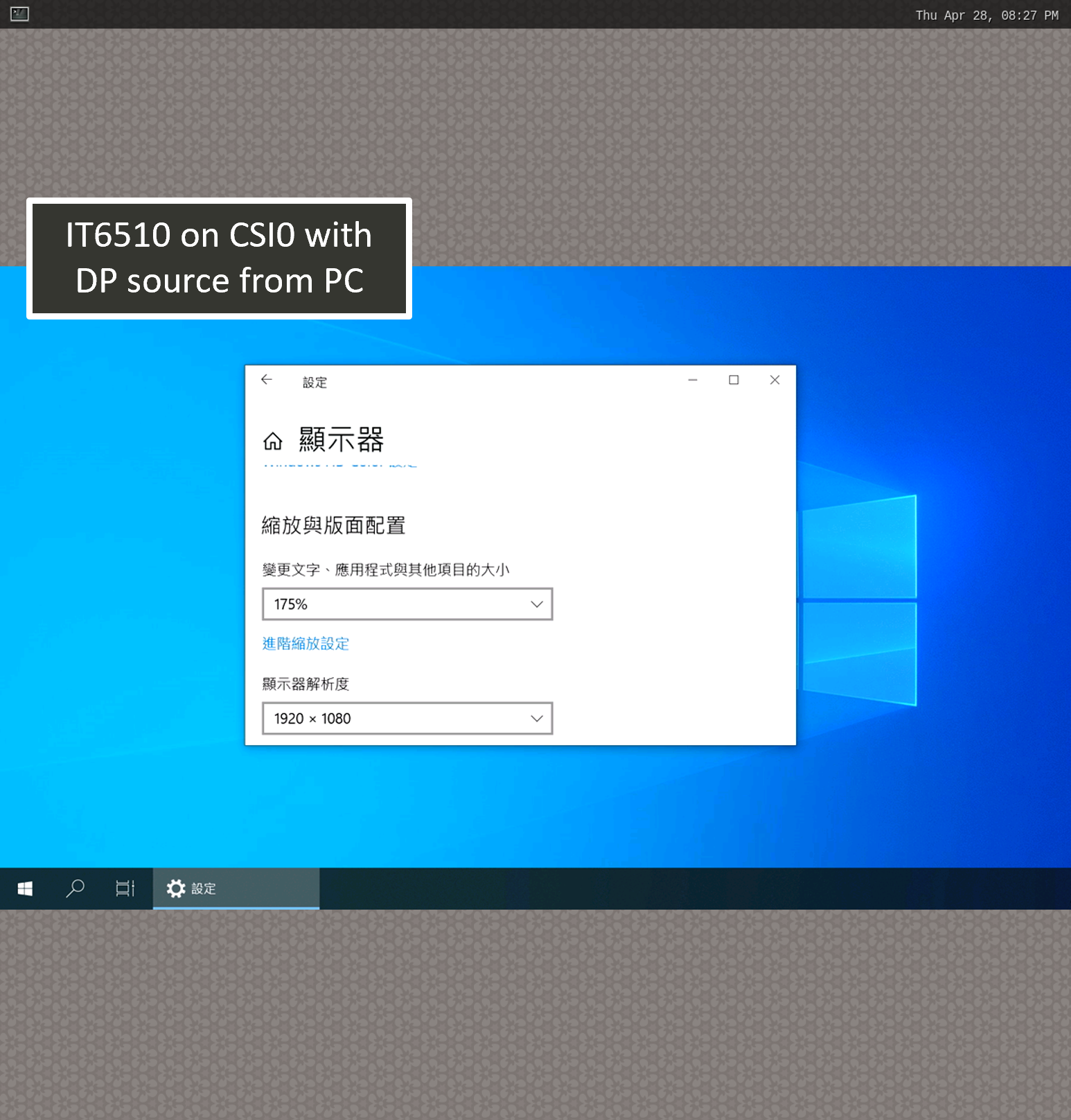
Single ITE IT6510 shown on the Weston desktop