FAQ
This pages collects frequently ask questions regarding IoT Yocto.
Genio 350
Why does HDMI not work on Genio 350 EVK?
Please refer to HDMI Does Not Work on Genio 350-EVK.
Does MT8365(Genio 350) BSP provide Contiguous Memory Allocator (CMA) support and reserve CMA area by default?
Yes, MT8365(Genio 350) BSP has CMA area allocated for common use.
The CMA area size is 32 MB by default and configured by kernel config CONFIG_CMA_SIZE_MBYTES=32.
Users could create further CMA areas for their own use.
[    0.000000] cma: Reserved 32 MiB at 0x00000000fa000000
[    0.000000] Memory: 2939124K/3145728K available (15552K kernel code, 2894K rwdata, 8552K rodata, 6272K init, 510K bss, 173836K reserved, 32768K cma-reserved)
Does MT8365(Genio 350) BSP support recovery boot mechanism, such as dual partition backup for bootloaders/kernel images?
No, MT8365(Genio 350) BSP does not support recovery boot mechanism.
How does MT8365(Genio 350) BootROM know which storage medium to boot from, for instance how does it know to boot from eMMC and not from NAND?
MT8365(Genio 350) BootROM polling boot devices by order, eMMC first and then NAND. If there is no eMMC device, the system will boot from NAND. MT8365(Genio 350) does not support using SD Card as a boot device.
Can MT8365(Genio 350) BootROM use any other boot region for booting besides mmc0boot0, for instance mmc0boot1 if mmc0boot0 got corrupted?
Yes, mmc0boot1 be used as the boot region, and BootROM will find an available boot region to boot.
In other words, if mmc0boot0 got corrupted and mmc0boot1 is available, the system will boot from mmc0boot1.
MT8365(Genio 350) uses systemd as default init system. Is it possible change to use sysvinit?
There is a page about init system configuration on Yocto user guideline:
https://docs.yoctoproject.org/3.1.16/ref-manual/migration-3.0.html?highlight=init_manager#init-system-selection
User could set the configuration INIT_MANAGER = “sysvinit” in local.conf to use sysvinit as init system.
Does MT8365 support MT6390 PMIC?
MT8365 supports MT6357 PMIC. The MT6390 PMIC is pin-to-pin compatible with MT6357 PMIC, but system software must adjust to different boot timing sequences. AIoT Open SDK currently does not support MT6390 PMIC.
Display function on Genio 350 doesn’t work well via MIPI
Please do the following:
check the hardware connection - is the “MB” side of the cable facing “up”, as shown in LCM Setup on Genio 350-EVK.
please provide dmesg log and let’s see if there are kernel warnings or errors.
Does Genio 350 support the landscape mode to rotate the 90 degree in MIPI-DSI?
On Genio 350(MT8365), the MIPI-DSI interface hardware itself does not support 90-degree frame buffer rotation. The OVL/RDMA hardware in the display data path also does not support hardware frame buffer rotation.
How to avoid the config overwritten during porting 3rd-party Connectivity Module?
Please do not revise the mt8365.cfg directly since the kernel module/driver is using the recipe method layer by layer in Yocto.
Both the upstream version of the mt7663 or the NDA version of the mt7663 driver are packaged by the recipe/include method.
The formal way should be to build its own kernel/service recipe for a 3rd Party’s connectivity module. Please refer to below modifications.
kernel driver recipes:
meta-mediatek-bsp/recipes-kernel/mt76xx-tk/mt76xx-tk-wifi-drv.bbmeta-mediatek-bsp/recipes-kernel/mtk-wireless-firmware/mtk-wireless-firmware_git.bb./meta-mediatek-bsp/recipes-kernel/linux/linux-mtk/mt76xx-tk-wifi.cfg./meta-mediatek-bsp/recipes-kernel/linux/linux-mtk/btmtksdio.cfg./meta-mediatek-bsp/recipes-kernel/linux/linux-mtk/mt7663.cfg
user space service recipe:
meta-mediatek-bsp/recipes-connectivity/mt7663/meta-mediatek-bsp/recipes-connectivity/mt7663/mt7663-service.bb
board support files:
meta-mediatek-bsp/conf/machine/mt8365-evk.conf:2:require include/mt7663.incmeta-mediatek-bsp/conf/machine/include/mt7663.inc
And please note that kernel common include need to be updated to include your config fragments.
Please refer to the following example of mt7663.cfg
in src/meta-mediatek-bsp/recipes-kernel/linux/linux-mtk-common.inc:
# Connectivity config fragments
SRC_URI:append:mt7663 = " \
        ${@bb.utils.contains('MT7663_WIFI_USE_UPSTREAM_DRV', '1', 'file://mt7663.cfg', 'file://mt76xx-tk-wifi.cfg', d)} \
        file://btmtksdio.cfg \
"
Genio 700
How to measure DVDD_MM, DVDD_GPU and DVDD_SRAM_GPU power on MT8390(Genio 700)?
It’s not possible to measure the power consumption of these paths when the module is not in use. DVDD_MM can be enabled by previewing the camera. Setup reference: Camera DVDD_GPU and DVDD_SRAM_GPU can be enabled by executing following command. Setup reference: Benchmark Suite
glmark2-es2-wayland
User can also refer to Stress Test Suite to enable most modules for power measurement.
How can I perform stereo recording using one DMIC pin on MT8390?
Take DMIC1 as an example, please follow the steps below:
Remove
dmic-clk-monofrom DTS and re-build the image.&afe { #sound-dai-cells = <0>; mediatek,dmic-iir-on; mediatek,dmic-clk-mono; status = "okay"; };Before recording, run the following commands:
amixer -c mt8390evk cset name='O002 I004 Switch' on
amixer -c mt8390evk cset name='O003 I005 Switch' on
amixer -c mt8390evk cset name='O003 I006 Switch' off
You can also refer to the DMIC user guide on MediaTek On-Line.
Document path: IoT/Software/Genio Series SoC/Genio 1200/IoT Yocto/Audio/MTK_MT8390_MT8395_IoT_Yocto_Audio_DMIC_Driver_User_Guide_v1.0.pptx
Enabling Auto Power On with Adapter on Genio 700 EVK
The version of Genio 700 EVK is printed on the back of the board.
If you are using Genio 700 EVK P1V2 or older:
Auto power on is enabled by default. The board always power on automatically if DC adapter is connected.
If you are using Genio 700 EVK P1V3:
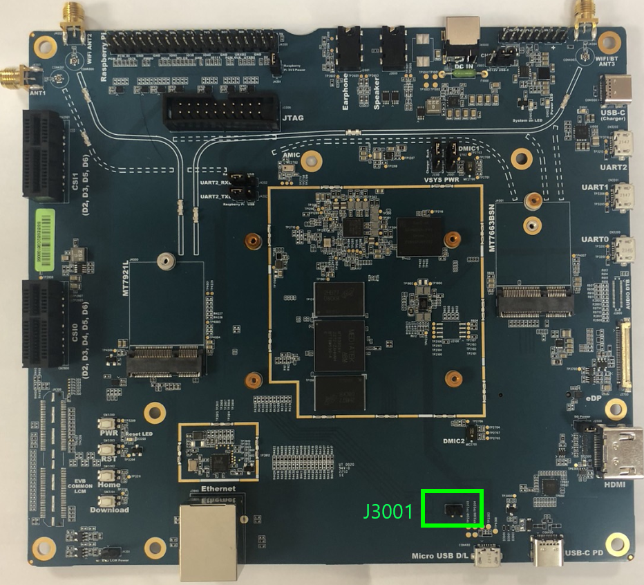
DC adapter auto power on can be disabled by removing the jumper on the J3001 jumper pins above the Micro USB D/L port.
When auto power on is disabled. Please press power key ( PWR ) to boot up system.
Please note that the board always power on automatically when the Micro USB D/L port is connected, regardless of the auto power on jumper setting.
For more information, please refer to the official Genio 700 EVK user guide in https://genio.mediatek.com/genio-700
Why does the I2S audio output from the IT6510FN have intermittent noise?
The noise is caused by incorrect eTDM master mode setting. By default, the I2S digital audio interface format on board is set to master mode. In this scenario, the I2S clock signal is transmitted from IT6510FN to G700-EVK/G1200-EVK, so G700-EVK/G1200-EVK should be configured in slave mode.
For more information, please refer to the eTDM configurations in eTDM user guide on MediaTek On-Line.
Document path: IoT/Software/Genio Series SoC/Genio 1200/IoT Yocto/Audio/MTK_MT8390_MT8395_IoT_Yocto_Audio_eTDM_Driver_User_Guide_v1.0.pptx
Genio 1200
How does MT8395(Genio 1200) BootROM know which storage medium to boot from?
MT8395(Genio 1200) BootROM supports polling mode for device booting, the polling sequence is eMMC –> UFS –> SPI NOR. If there is no eMMC device, the system will boot from the next storage medium. MT8395(Genio 1200) does not support using SD Card as a boot device.
How can I perform stereo recording using one DMIC pin on MT8395?
Take DMIC1 as an example, please follow the steps below:
Remove
dmic-clk-monofrom DTS and re-build the image.&afe { #sound-dai-cells = <0>; mediatek,dmic-iir-on; mediatek,dmic-clk-mono; status = "okay"; };Before recording, run the following commands:
amixer -c mt8395evk cset name='O002 I004 Switch' on
amixer -c mt8395evk cset name='O003 I005 Switch' on
amixer -c mt8395evk cset name='O003 I0010 Switch' off
You can also refer to the DMIC user guide on MediaTek On-Line.
Document path: IoT/Software/Genio Series SoC/Genio 1200/IoT Yocto/Audio/MTK_MT8390_MT8395_IoT_Yocto_Audio_DMIC_Driver_User_Guide_v1.0.pptx
Enabling Auto Power On with Adapter on Genio 1200 EVK
The version of Genio 1200 EVK is printed on the back of the board.
If you are using Genio 1200 EVK P1V1:
DC adapter Auto power on is enabled when USB-C D/L port is plugged in. DC adapter Auto power on is disabled when USB-C D/L port is not plugged in. Please press power key (
PWR) to boot up system.If you are using Genio 1200 EVK P1V2:
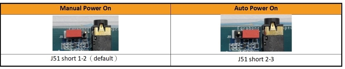
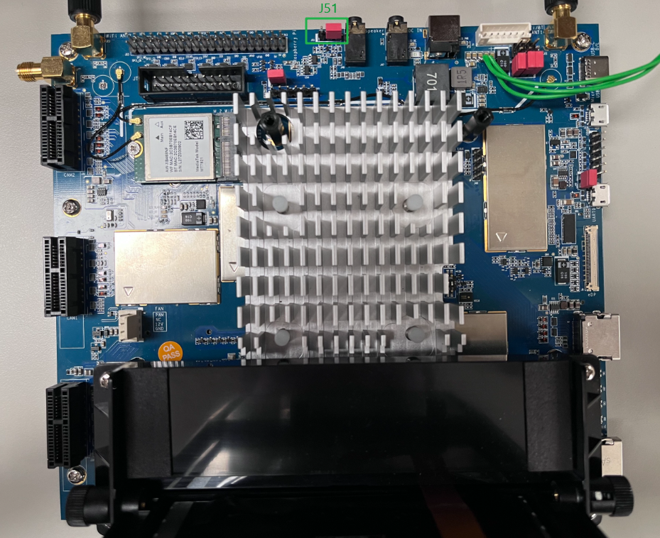
DC adapter auto power on can be enabled by moving the jumper on
J51jumper pins to short 1-2 (see the image below). DC adapter auto power on can be disabled by moving the jumper onJ51jumper pins to short 2-3 (see the image below). When auto power on is disabled. Please press power key (PWR) to boot up system.
Please note that the board always power on automatically when the USB-C D/L port is connected, regardless of the auto power on jumper setting.
Why does the I2S audio output from the IT6510FN have intermittent noise?
The noise is caused by incorrect eTDM master mode setting. By default, the I2S digital audio interface format on board is set to master mode. In this scenario, the I2S clock signal is transmitted from IT6510FN to G700-EVK/G1200-EVK, so G700-EVK/G1200-EVK should be configured in slave mode.
For more information, please refer to the eTDM configurations in eTDM user guide on MediaTek On-Line.
Document path: IoT/Software/Genio Series SoC/Genio 1200/IoT Yocto/Audio/MTK_MT8390_MT8395_IoT_Yocto_Audio_eTDM_Driver_User_Guide_v1.0.pptx
Software
Why does IoT Yocto take several hours to build the first time?
The build system have to fetch various software components from servers specified in recipes. Usually it takes 30 minutes to one hour to fetch sources, depending on your internet connection speed, and the capacity of the remote servers. It might take longer when fetching a large project such as OpenCV.
The downloaded software component sources are stored in a download folder (specified in DL_DIR variable). Since the content can be reused by each build, we recommend you to keep the folder, even if the build directory has changed. You can specify different path of download folder in DL_DIR variable in your local.conf or site.conf.
Why does BitBake fail to fetch NDA repositories even though I have GitLab permissions?
If you have confirmed your account permission, but the bitbake command still shows a fetch error:
do_fetch: Bitbake Fetcher Error: FetchError('Unable to fetch URL from any source.', 'git://git@gitlab.com/mediatek/aiot/nda/xxxxxx.git;protocol=ssh;branch=main')
You might want to check the following settings:
In
~/.netrc, make sure there are no incorrect machine entries pointing togitlab.com.Try resetting your git credential cache. If you are using the
storecredential helper, you can try resetting the storage:git config --unset credential.helper git config --global --unset credential.helper git config --global credential.helper store
Where can I find the Yocto recipes and dtbo files used in the prebuilt images?
Let’s have an overview on all the Yocto meta layer used in Genio’s IoT Yocto codebase. To do so, you can visit the manifest file of each release. For example, the v22.2 release’s manifest file can be found in
https://gitlab.com/mediatek/aiot/bsp/manifest/-/blob/rity-kirkstone-v22.2/default.xml
In the XML manifest file, you can find these Yocto meta layer repositories:
meta-armmeta-clangmeta-mediatek-bspmeta-mediatek-demometa-mediatek-tsnmeta-nnmeta-openembeddedmeta-qt5meta-ritymeta-stress-testmeta-tensorflowpoky
The meta layers hosted in https://gitlab.com/mediatek/aiot/rity are provided and maintained by MediaTek. Other meta layers are maintained by third-party and used by IoT Yocto.
The essential meta-layers for the Genio boards are:
meta-mediatek-bsp is the “core” layer that provides Genio SoC and Board support, including recipes for Linux kernel (
linux-mtk), bootloader, and MediaTek middleware.meta-rity is the “top level wrapper” layer for image recipes. All IoT Yocto image recipes, including rity-demo-image, rity-bsp-image, rity-bringup-image are defined here. The
TEMPLATECONFfor initial build environment used bypoky/oe-init-build-envis also defined here.
Therefore, to locate the DTBO, config fragments(.cfg) and kernel recipe, you could find them in: https://gitlab.com/mediatek/aiot/rity/meta-mediatek-bsp
To locate the exact configurations for each machine, you could dig into: https://gitlab.com/mediatek/aiot/rity/meta-mediatek-bsp/-/tree/kirkstone/conf/machine
And you’ll find some of the machines are aliases to each other. For example, the config file for Genio 1200-EVK:
is a symbolic link to:
which contains the following MACHINEOVERRIDES definition:
MACHINEOVERRIDES =. "mt8395-evk:genio-1200-evk:"
With this in mind, you can locate the DTBO files in recipes-kernel/dtbo
For example, the DTBO used in the command:
genio-flash --load display-dp.dtbo
can be found here.
My rootfs is too small, how do I make it larger?
The BSP does not specify any storage size, so the rootfs will be just large
enough to contain the content built by the Yocto image. If you need to
increase the size the size of the rootfs you can add the following to your
local.conf:
IMAGE_ROOTFS_EXTRA_SPACE = "500000" # KBytes
IMAGE_ROOTFS_EXTRA_SPACE can be set to increase the amount of free disk space in the rootfs partition.
For more information you can check the Yocto Reference Manual.
My home partition is too small, how do I make it larger?
You can set the home partition size by setting the following variable in
your local.conf:
IMAGE_HOME_SIZE = "500M"
How do I add additional applications to my image?
If you want to add new applications to your image you can set the following variable in your local.conf:
IMAGE_INSTALL:append = " \
    gdb              \
    htop             \
"
The example above will add gdb and htop to the image that gets built by bitbake.
Why can I not connect to the board by ssh over USB on Windows
By default the BSP uses the USB gadget ecm to provide a network interface over USB. Windows does not support well ecm. So if you plan to connect to the board by ssh over USB on Windows, please refer to Communicating with the Board.
Why does the error message “ERROR:aiot:No image found” shows when I flash a single partition with genio-flash <partition> command?
The reason “ERROR:aiot:No image found” appears may be because genio-flash cannot find rity.json.
rity.json will indicate the correspondence between partition and image filename.
genio-flash process refers to this file to find the corresponding image.
This file would only be generated after a full build (rity-demo-image) is done.
After the file is generated, you can flash the single partition (e.g, kernel or bootloaders) individually with using genio-flash <partition> command.
"partitions": {
      "mmc0": null,
      "mmc0boot0": "bl2.img",
      "mmc0boot1": "u-boot-env.bin",
      "bootloaders": "fip.bin",
      "kernel": "fitImage",
      "rootfs": null
},
What is the default partition size in MT8365(Genio 350) BSP?
The default partition size is listed in the table below.
Partition name |
Size |
|---|---|
mmc0boot0 |
4MB |
mmc0boot1 |
4MB |
bootloaders |
4MB |
kernel |
15MB |
rootfs |
depend on the user space stuffs. (~1467 MB in rity-demo-image) |
home |
273 MB in rity-demo-image |
How do I adjust each partition size in detail?
You can modify the system partition configuration file in meta-rity/meta/wic/rity.wks.in.
The configuration file is written in Yocto kickstart format.
Here is an online guideline for Yocto kickstart(.wks): https://docs.yoctoproject.org/ref-manual/kickstart.html
Note that the partition size of mmc0boot0 and mmc0boot1 are not able to be modified.
How to update rootfs partition only instead of updating full system image?
In IoT Yocto build configuration, we configure wic.img in IMAGE_FSTYPES only and it will integrate all system images into one wic.img file.
If you would like to update rootfs partition only, you could add ext4 to IMAGE_FSTYPES in mediatek-common.inc and it would make Yocto to build an additional ext4 file for rootfs.
src/meta-mediatek-bsp/conf/machine/include/mediatek-common.inc
-IMAGE_FSTYPES ?= "wic.img"
+IMAGE_FSTYPES ?= "wic.img ext4"
Besides, Rootfs is split over two partitions in IoT Yocto: rootfs and home. The ext4 file contains all of them at once. You have to increase GPT rootfs partition size.
Then, you can use the genio-flash command below to partially update the rootfs and kernel partitions.
genio-flash system
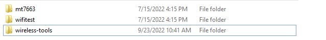
Open Source Tools iwpriv (from legacy wireless-tools) for MT7663
Recipe URL
https://hewlettpackard.github.io/wireless-tools/Tools.html
SOP
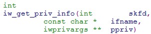
Add iwpriv tool
.bbfile into connectivity recipe
Executed build command to get code and build bin tool out


Modify tool source code to enlarge the MAX size that allowed for driver ioctl and rebuild tool (without this step, the tool will print “no private ioctl” error message.)
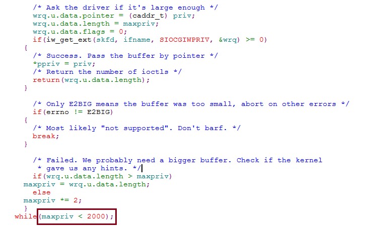
After above steps, iwpriv tool is available.
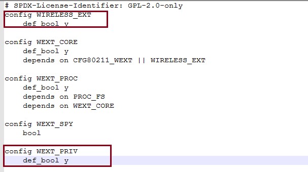
Then we need to modify kernel configuration to let iwpriv tool available for all commands used in mt76-tk-driver. (Without this step, iwpriv driver command cannot be used)
Set config WIRELESS_EXT to def_bool y
Set config WEXT_PRIV to def_bool y

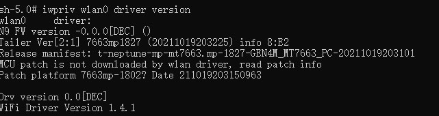
Rebuild load and all done. User can execute iwpriv wlan0 driver version to confirm whether it is OK.
I tried to download source code from GitLab. Why do I get the following error: Host key verification failed. Fatal: Could not read from remote repository?
There are multiple factors affecting your connection to GitLab. Please follow steps below to diagnose the issue:
Check git HTTP/HTTPS protocol:
Can you run the following command in your Ubuntu machine to fetch the repository directly?
git clone https://gitlab.com/mediatek/aiot/rity/meta-mediatek-bsp.gitThe output should look like:
Cloning into 'meta-mediatek-bsp'...
remote: Enumerating objects: 7604, done.
remote: Counting objects: 100% (243/243), done.
remote: Compressing objects: 100% (141/141), done.
remote: Total 7604 (delta 137), reused 170 (delta 94), pack-reused 7361
Receiving objects: 100% (7604/7604), 1.15 MiB | 2.41 MiB/s, done.
Resolving deltas: 100% (4953/4953), done.
Confirm git SSH protocol:
Can you run the following command in your Ubuntu machine to fetch the repository directly via SSH?
Precondition: Make sure you have a GitLab account and have added your SSH key to GitLab first.
git clone git@gitlab.com:mediatek/aiot/rity/meta-mediatek-bsp.gitIf you succeeded in step 1, but failed in step 2, it might indicate that your firewall settings are blocking SSH connections. In this case, please try step 3:
Use git protocol re-direction:
Run the following command on your Ubuntu machine:
git config --global url.'http://gitlab.com'.insteadOf 'ssh://git@gitlab.com'This would enforce all the SSH connection from
gitprogram togitlab.cominto HTTP protocols. After running the command, please check step 2 again.It should work if your step 1 works. If this works,
repo syncshould also work, because it basically callsgit clonefor you.
Why does kmscube command return with “failed to set mode: Permission denied”?
kmscube creates its own window on which it renders content. So, before we launch kmscube, we must make sure that no other window system occupies the display. This means stopping the Weston process that drives the desktop.
systemctl stop weston
Windows PC can’t recognize USB Driver
There are multiple protocols available on AIOT reference EVK’s USB ports.
Fastboot is both a protocol and a tool. It does originate from Android platform, but in IoT Yocto, we use Fastboot to flash image from USB to on-board EMMC (or UFS). This is the reason why we ask you to install Fastboot driver (named Android Bootloader Interface under Windows 10) before flashing your board.
ADB (Android Debugging Bridge) is also both a protocol and a tool. The goal of ADB is to provide a debugging link between the target board and host PC. As of v21.3.1, we do not provide ADB support on rity-demo-image. However, that is something we plan to add in v22.0.
Please note that not all ADB / Fastboot functions are supported on Yocto. For example, it is impossible for Yocto to support adb setprop, because Yocto does not have Android property system. Basic commands such as adb push, adb pull, adb shell could be supported.
For CDC-ECM, it is an USB Ethernet device to allow you to establish IP network link between target board and host PC. Unfortunately, Windows does not provide good support for CDC-ECM devices. You can use RNDIS device instead, please refer to RNDIS.
Systemd Log (journalctl) disappears after reboot. How to make them persist?
By default, Yocto maps /var/log to /volatile/log, and therefore all journal logs are dropped after system reboot.
To keep them after rebooting, add this line:
VOLATILE_LOG_DIR="no"
to your <build-dir>/conf/local.conf file and rebuild the image. After flashing and rebooting the target board,
make sure that you have a /var/log/journal directory generated.
The log displayed by journalctl should persist after rebooting the board.
reference: https://docs.yoctoproject.org/4.0.7/ref-manual/variables.html#term-VOLATILE_LOG_DIR
Why does the error message “aarch64-poky-linux-g++: fatal error: Killed signal terminated program cc1plus” appear when I build a Yocto image?
When you encounter this error message aarch64-poky-linux-g++: fatal error: Killed signal terminated program cc1plus, it means that your build server has run out of memory.
This is because BitBake uses parallelism during the build process, and too many build threads were running simultaneously, which exhausted the server’s memory.
Following is the snapshot of error message:
{standard input}:444958: Warning: end of file not at end of a line; newline inserted
{standard input}:444959: Error: invalid address at operand 2 -- `ldr x2,'
{standard input}: Error: open CFI at the end of file; missing .cfi_endproc directive
aarch64-poky-linux-g++: fatal error: Killed signal terminated program cc1plus
To optimize the number of tasks that BitBake can perform in parallel at any one time, you can set the BB_NUMBER_THREADS variable
in your local.conf file. If your host development system supports multiple cores, a good rule of thumb is to set this variable to twice the number of cores.
BB_NUMBER_THREADS = "16"
How to add multiple spidevs on multiple SPI buses?
Linux support to enable two or more spidev instances on different SPI bus at the same time. Please refer to the following DTS example.
&spi0 {
    /* ignore other properties */

    spidev0: spidev@0 {
        compatible = "mediatek,aiot-board";
        spi-max-frequency = <5000000>;
        reg = <0>;
    };
};

&spi1 {
    /* ignore other properties */

    spidev1: spidev@0 {
        compatible = "mediatek,aiot-board";
        spi-max-frequency = <5000000>;
        reg = <0>;
    };
};
How to write the FW into eMMC if the eMMC is empty?
Genio Tools supports eMMC programming even when the eMMC is empty.
All Genio SoCs have an embedded Boot ROM (BROM) that is used to bootstrap the system.
The flash tool, Genio Tools, actually depends on the download mode
provided by the BROM. This download mode allows the flash tool to upload a download agent
program (lk.bin in prebuilt images) to the SoC SRAM using USB0 port. The download agent is then responsible for
the subsequent boot strapping and flash programming operations.
As a result, you could always program the eMMC storage using Genio Tools, regardless of the content on the eMMC storage.
For production purposes, the download mode could be disabled by blowing a SoC eFuse field to make the USB port more temper-resistant. The download agent could also be signed for secure-boot scenarios. Please refer to Secure Boot for details.
A failure happens with a message “'features.h' file not found” when building clang
This issue is caused by the way of handling debugging flags in the CMakeLists.txt provided by the upstream llvm-project.
Customers often put their IoT Yocto codebase under the paths containing the string
“MTK” (/home/user1/MTK/yocto for example). When building clang, the string
replacing operation in the CMakeLists.txt mentioned above accidentally removes the
substring /MT from the header search paths, which becomes /home/user1K/yocto/...,
thus causes the failure.
As a workaround, please do not checkout the codebase under the path containing
substrings such as /D_DEBUG, /MTd, /MDd, /MT, and /Md.
How can I debug via USB port on the board?
The USB0 port is configured with several USB devices for debugging.
Please refer to Connecting Board to Host for details.
Is it possible to dump U-Boot log by adb?
No, dumping U-Boot log from ADB is not supported because:
The U-Boot in IoT Yocto does not support USB Peripheral driver.
The U-Boot in IoT Yocto does not have the function to support ADB protocol.
How can I use a USB VCOM to debug the board?
IoT Yocto does not enable USB VCOM by default. To enable a debugging console with USB VCOM in Linux, there are 2 steps involved:
Create an
acmUSB gadget in Linux USB gadget configfs framework to create a USB virtual COM port device. IoT Yocto v23.1 has the Linux kernel optionCONFIG_USB_CONFIGFS_F_FSenabled by default, and all Genio EVKs utilize configfs to create ADB devices. Therefore you could simply extend the fileusbgadget.shinmeta-rityto create aacm.GS0node:diff --git a/meta/recipes-core/base-files/files/usbgadget.sh b/meta/recipes-core/base-files/files/usbgadget.sh index ab1d3c5..0757e03 100644 --- a/meta/recipes-core/base-files/files/usbgadget.sh +++ b/meta/recipes-core/base-files/files/usbgadget.sh @@ -5,6 +5,7 @@ USB_GADGET_G1=/sys/kernel/config/usb_gadget/g1 USB_GADGET_G1_CONF=$USB_GADGET_G1/configs/c.1 USB_GADGET_G1_FUNC=$USB_GADGET_G1/functions USB_GADGET_ADB=adb +USB_GADGET_CDC=cdc USB_GADGET_RNDIS=rndis USB_GADGET_BCDUSB=0x0200 USB_GADGET_BCDDEV=0x0233 @@ -22,12 +23,15 @@ create_gadget() mkdir -p $USB_GADGET_G1/strings/0x409 mkdir $USB_GADGET_G1_FUNC/rndis.usb0 mkdir $USB_GADGET_G1_FUNC/ffs.adb + mkdir $USB_GADGET_G1_FUNC/acm.GS0 mkdir -p $USB_GADGET_G1/strings/0x409 mkdir -p $USB_GADGET_G1_CONF/strings/0x409 mkdir $USB_GADGET_DEV -m 770 mkdir $USB_GADGET_DEV/adb -m 770 + + ln -s $USB_GADGET_G1_FUNC/acm.GS0 $USB_GADGET_G1_CONF } set_gadget_sn() @@ -77,7 +81,7 @@ set_gadget() echo 1 > os_desc/use echo "MSFT100" > os_desc/qw_sign - echo $USB_GADGET_RNDIS+$USB_GADGET_ADB > configs/c.1/strings/0x409/configuration + echo $USB_GADGET_RNDIS+$USB_GADGET_ADB+$USB_GADGET_STOR+$USB_GADGET_CDC > configs/c.1/strings/0x409/configuration ln -s functions/rndis.usb0 configs/c.1 ln -s functions/ffs.adb configs/c.1 @@ -117,6 +121,7 @@ stop() rm $USB_GADGET_G1_CONF/rndis.usb0 rm $USB_GADGET_G1_CONF/ffs.adb + rm $USB_GADGET_G1_CONF/acm.GS0 umount /dev/usb-ffs/adb }
The configuration above creates an USB VCOM in the USB0 port. After rebooting the system, a
ttyGS0device should appear:# ls /dev | grep ttyGS ttyGS0For details of configfs, please refer to here.
Set up Linux serial console configuration to create a console in
ttyGS0. This can be done by configuring the SERIAL_CONSOLE variable in Yocto’s config file<build_dir>/conf/local.conf:SERIAL_CONSOLES:append = " 921600;ttyGS0 "
This configuration makes Yocto BitBake system to create a systemd unit file for serial-getty service. Note that if you remove the
:appendsuffix:SERIAL_CONSOLES = " 921600;ttyGS0 "
Then the default serial console,
ttyS0(UART0), will be disabled and UART0 will have no login console.
How to disable CPU core manually?
The MediaTek Genio platform supports CPU hot-plugging. The Linux kernel will disable the CPU core when the system load is low. However, if you wish to manually disable the CPU core due to an experiment or any other purpose, you can do so using the following commands.
# Disable CPU core
echo 0 >  /sys/devices/system/cpu/cpu$i/online  # Here, `$i` represents the CPU core ID.
# Enable CPU core
echo 1 >  /sys/devices/system/cpu/cpu$i/online  # Here, `$i` represents the CPU core ID.
Why can’t I always use a fixed video node (e.g. /dev/video5) as the camera input?
The assigned node number for the video device may vary depending on the sequence of the probing process during the boot-up phase.
As such, it is crucial to ensure the accuracy of the video device node prior to commencing the usage of the camera.
The v4l2-ctl tool is a useful utility that can assist in identifying the specific video device node you are looking for.
# Use v4l2-ctl to list all video device
v4l2-ctl --list-devices
In the user application implementation, it is better to enumerate all available video device nodes and search for the desired node based on its name and expected capabilities. For more information about querying the capability, please refer to Querying Capabilities.
How to change baudrate of the UART0 port?
Each boot phase has its own UART0 port configurations for log output. The default configuration of the IoT Yocto BSP sets the baudrate to 921600 except for boot ROM phase. The following sections shows you how to change the baudrate of each phase to 115200.
Boot ROM UART0 Baudrate
The baudrate for Boot ROM log is fixed to 115200 and cannot be changed by software configuration.
BL2 Baudrate
The baudrate for BL2 (TF-A) is defined as a macro in the following path under the TF-A repository:
plat/mediatek/<platform>/include/platform_def.h
To change the baudrate of UART0 port during BL2 (Trusted-Firmware for ARM) phase, search for the UART_BAUDRATE macro and modify it
to 115200, for example:
#define UART_BAUDRATE 115200
U-Boot Baudrate
The baudrate of the U-Boot log can be changed dynamically by setting the baudrate U-Boot environment variable.
For example, you can change the baud rate to 115200 in IoT Yocto command shell with the following commands:
setenv baudrate 115200
saveenv
You could also configure the baudrate U-Boot environment variable during “image flashing” stage,
by adding the following line in the u-boot-initial-env file:
baudrate=115200
and then re-flash the image.
To change the U-Boot baudrate during build time, locate the following config file in the U-Boot repository:
configs/<board>_defconfig and modify the configuration variable CONFIG_BAUDRATE:
CONFIG_BAUDRATE=115200
You should replace the board configuration file name <board>_defconfig to the board that you’re using, e.g.
genio_1200_evk_defconfig.
Linux Kernel Console Baudrate
There are several ways to change the UART baudrate of the Linux kernel console.
To set it as part of the device tree, add or modify the stdout-path value in the chosen node of the board DTS file.
For example, to change the Linux serial console default baudrate of the Genio 1200 EVK board, modify
the file arch/arm64/boot/dts/mediatek/genio-1200-evk.dts and change the chosen node as the following values:
chosen {
    stdout-path = "serial0:115200n8";
};
For details, please refer to the kernel documentation of the chosen node.
Login Shell Consoles
For the baudrate settings of UART login shell consoles, you need to modify the Yocto recipe variable SERIAL_CONSOLES . The default setting for Genio boards are defined in the following recipe configuration file:
src/meta-mediatek-bsp/conf/machine/include/mediatek-common.inc
To change the baudrate, modify the line SERIAL_CONSOLES:
SERIAL_CONSOLES = "115200;ttyS0"
Or override the variable in your own BSP layer recipes.
How to debug GPIO in U-Boot and kernel ?
This FAQ provides detailed instructions on how to debug GPIO in u-Boot and kernel. It covers the usage of specific commands to set and read GPIO status.
U-Boot GPIO debug command
To debug GPIO in U-Boot, use the gpio command.
Ensure the following configurations are enabled in your U-Boot config:
CONFIG_PINCTRL_MTK=y
CONFIG_PINCTRL_MTXXXX = y
CONFIG_CMD_GPIO=y
Usage:
Set GPIO10 as output-high:
gpio set 10
Set GPIO10 as output-low:
gpio clear 10
Set GPIO10 as input:
gpio input 10
View the status of all GPIOs:
gpio status -a
Kernel GPIO debug command with libgpiod
The libgpiod command can be used to control GPIOs in the kernel.
(Note: You can replace gpiochip0 with 0.)
Usage:
gpioinfo: List GPIO information, including input/output status and whether they are in use.gpioinfo gpiochip0gpioget: Read the value of a GPIO, setting the mode to GPIO and direction to input before reading the input value.# gpioget [OPTIONS] <chip name/number> <offset 1> <offset 2> ... # Set GPIO26 as input and read its value gpioget gpiochip0 26
gpioset: Set a GPIO as output-low or output-high, and sets the mode to GPIO.# gpioset [OPTIONS] <chip name/number> <offset1>=<value1> <offset2>=<value2> ... # Set GPIO26 to low level, output-low gpioset gpiochip0 26=0 # Set GPIO26 to high level, output-high gpioset gpiochip0 26=1
Dump GPIO status in kernel
Usage:
For Genio 700/1200:
cat /sys/kernel/debug/pinctrl/10005000.pinctrl-xxxx/pins