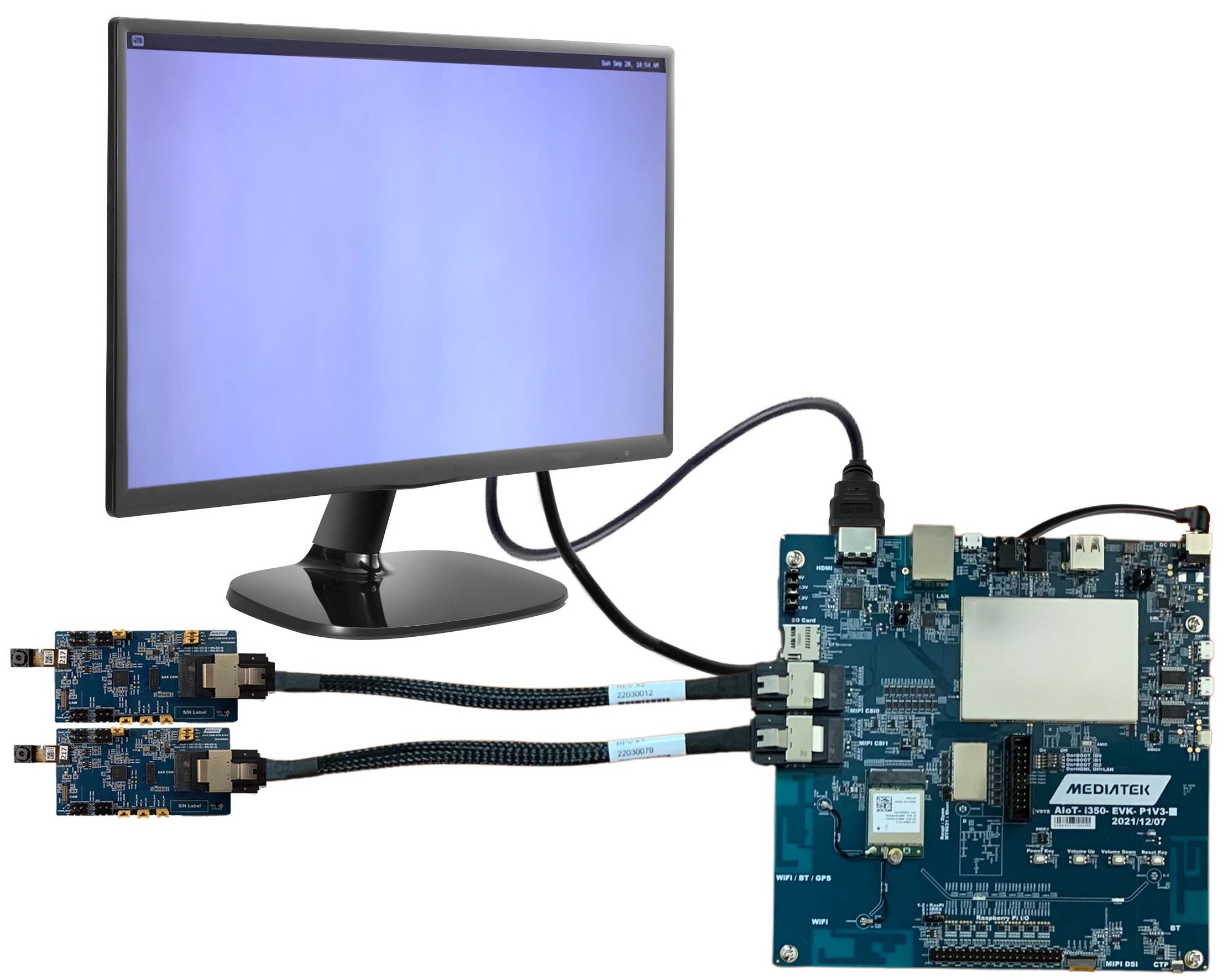
Genio 350-EVK Demo
This demonstration kit is very flexible and can be setup in various configurations, with software support for Android. However for the purpose of this Quick Start Guide, a specific configuration is chosen with the following conditions:
Android software build
Both AP1302 ISP Camera Boards and Appletec AR0430 Camera Modules enabled
AP1302 ISP Camera Board configured to use the On-Semiconductor AP1302CSSL00SMGA0-DR ISP
External HDMI Monitor (not the included TFT LCD Module)
Ethernet interface disabled
Additional Items Needed for Quick Start Guide Demo
To support the demo, the following additional items are needed.
External Monitor supporting HDMI
HDMI Cable
Two USB Cables (USB-2.0-A to Micro-B)
External PC for loading flash and interacting via command prompt
Genio 350-EVK Demo System Image
Setup PC Environment
Install the Genio Tools on your Linux or Windows PC.
Kit Hardware Installation
Insert AzureWave Wireless Module and two corresponding jumper wires as shown in AzureWave Wireless Module. The jumper wires connect the module to the on board PCB antennas.
Insert Mini-SAS Cable into the corresponding connectors of the Genio 350 EVK mainboard and Camera board.
Connector locations can be referred to the marks in the picture as below.
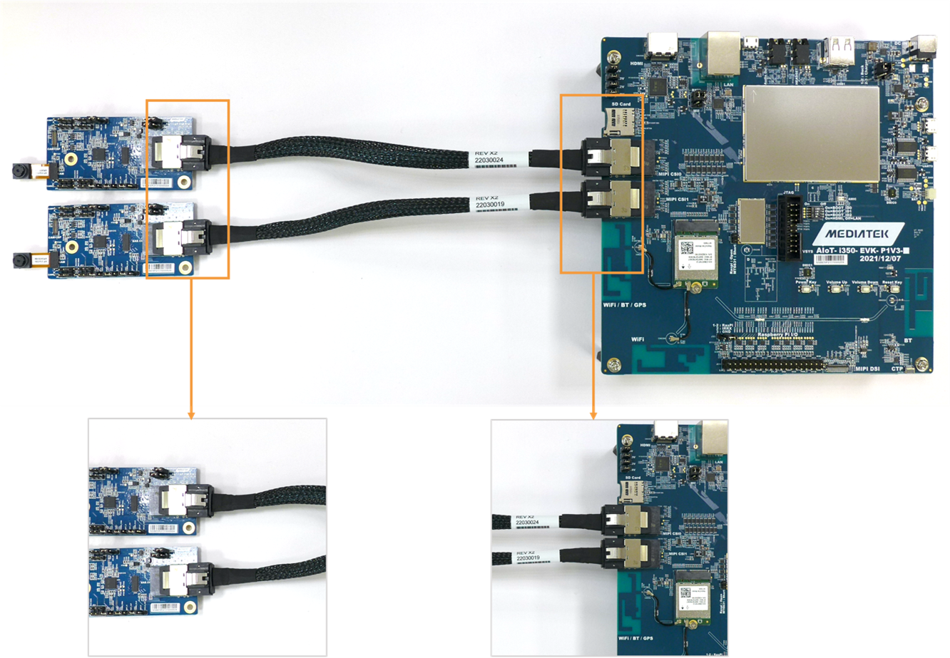
Camera Board Installation
Note
You should hear a “click” sound to confirm when the Mini-SAS cables have been correctly inserted into the connectors.
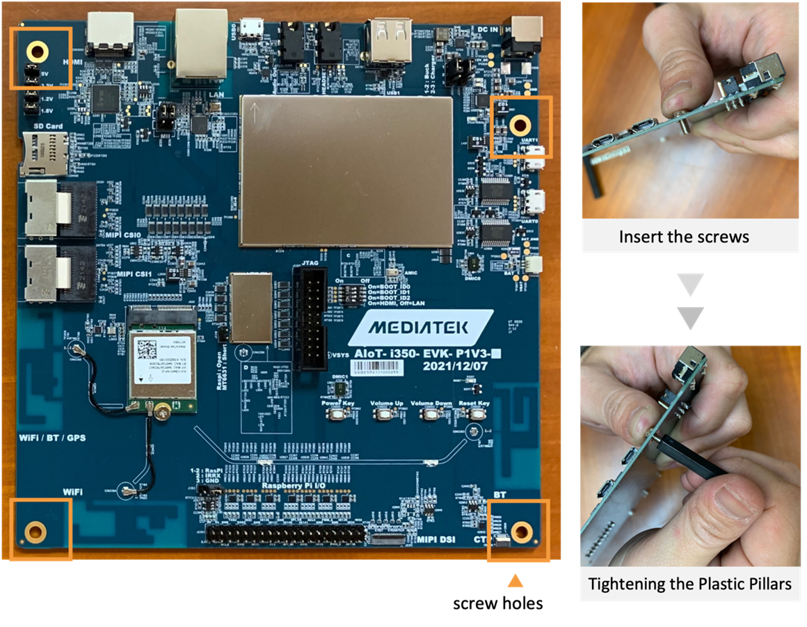
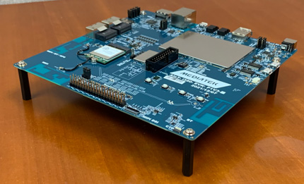
Insert the screws into the screw holes on the front of the Genio 350EVK mainboard and screw the plastic standoffs from the back.
Connect a USB cable to connector labeled UART0 as shown in: Genio 350 EVK Main Motherboard.
This requires installation of the Google Android USB driver as outlined in the Setup PC Environment section. If using Windows, open Device Manager and confirm that the driver appears under Android Device \ Android Bootloader Interface.
Connect a second USB cable to USB0
This requires installation of the FTDI VCP USB driver as outlined in the Setup PC Environment section. If using Windows, open Device Manager and confirm that the driver appears under Ports (COM & LPT) \ USB Serial Port (COMx), where x is the port assigned by your system.
Further details regarding both USB drivers can be found in the flash trouble-shooting section.
Plug AC/DC power adapter into the connector.
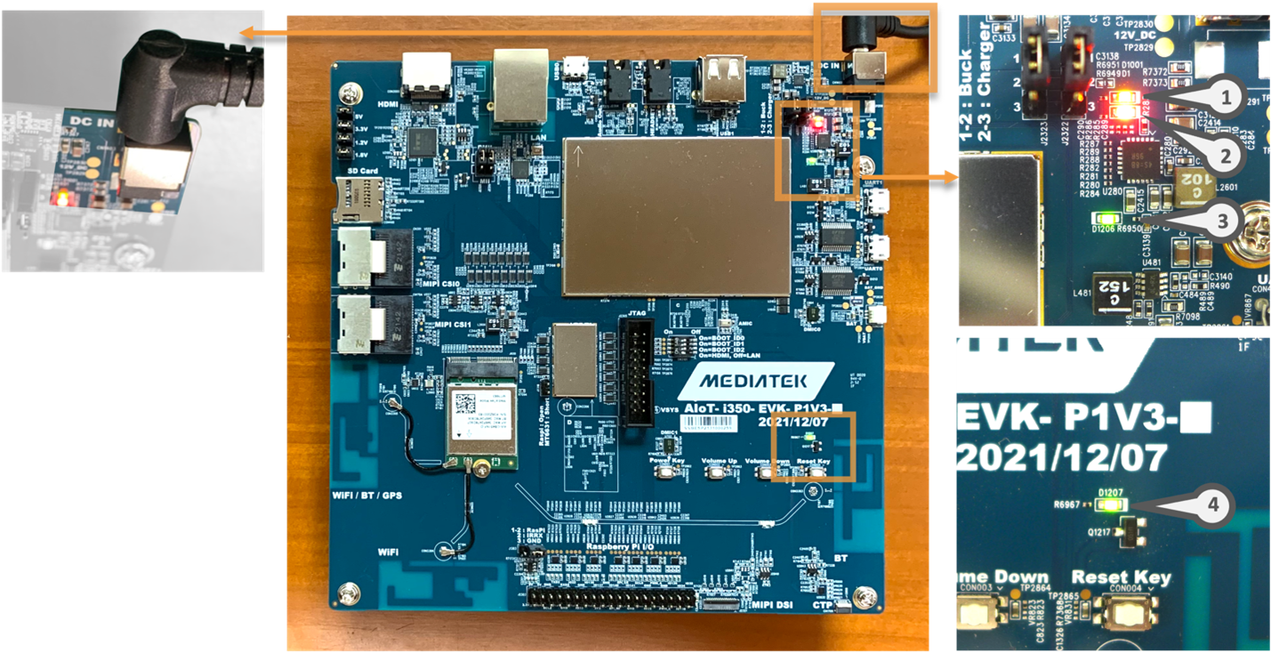
Power Adapter Installation
Note
After the EVK power is turned on, confirm that the four LED indicators illuminate.
Connect to the Serial Console
Setup the serial port for viewing debug output and interacting with the kit through a command line interface.
Check Device Manager that the USB COM port appears as a UART device under COM Ports
Configure your installed serial terminal emulator to use the serial port corresponding to the devices UART0 and operating with the baud rate set to 921600.
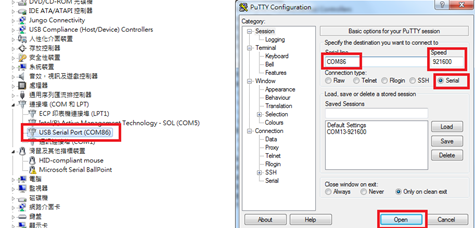
Example with Putty
Use dmesg to determine which USB serial ports have recently been connected:
dmesg | grep tty [299443.861514] usb 2-4.2.1: FTDI USB Serial Device converter now attached to ttyUSB0In this instance, the serial terminal is
ttyUSB0, which will be present under/dev/Connect to the device using a baud rate of
921600, for example, with Picocom:picocom -b 921600 /dev/ttyUSB0
Flash the Software
This guide shows how to “flash” (write) the demo image into the non-volatile flash memory of Genio 350-EVK. The flashing process is performed through the USB0 connection on the Genio 350-EVK. In order to write the on-board storage with Genio Tools, you need to set the IoT SoC in download mode, which allows Genio Tools to transfer a download agent binary to the SRAM of SoC. The download agent then provides a fastboot interface for subsequent image transfer and storage write operations.
Download the pre-built board image to your local PC.
Unzip the image.
Note
Avoid having a long path name by installing to a root folder and shortening the file name if necessary, for example C:\\evk.
Open a Windows cmd window (to enter commands)
Change working folder to the image directory before running the
genio-flashcommands:
cd C:\evk
View the Flash Image to Board instructions for further details or troubleshooting.
Once you see the
Looking for a MediaTek SoC ...prompt, start the process to boot the board in flash download mode.
Press and keep pressing the volume up button
Press and release the reset button
Release the volume up button
Reset the board to enter download mode
Note
On most Genio evaluation boards, the volume up button is connected to the KPCOL0 pin of the chip. If you have trouble finding the correct button, refer to the user guide or schematics of your board.
You should see flashing process started after releasing the volume up button. A typical successful log looks like this:
Genio Tools: v1.6a3
    Raw Image:
                    name:  eMMC Disk Image (Sparse Image)
                    machine:  Unspecified

    WARNING:root:Cannot find any FTDI device
    WARNING:root:Unable to find and reset the board. Possible causes are:
    1. This is not a Genio 350/700 EVK, nor a Pumpkin board.
    2. The board port UART0 is not connected.
    3. The UART0 port is being opened by another tool, such as TeraTerm on Windows.
    You can now manually reset the board into DOWNLOAD mode.

    INFO:root:Continue flashing...
    Looking for MediaTek SoC matching USB device 0e8d:0003
    Opening COM8 using baudrate=115200
    Connected to MediaTek SoC: hw_code[0x8168]
    Sending bootstrap to address: 0x201000
    Jumping to bootstrap at address 0x201000 in AArch64 mode
    erasing mmc0
    < waiting for any device >
    Erasing 'mmc0'                                     (bootloader) request sz: 0xe8f800000, real erase len: 0x0
    OKAY [  0.062s]
… (shortened for brevity)
Rebooting                                          OKAY [  0.002s]
Finished. Total time: 0.003s
Once the kit boots up with the new flash image, debug log messages can be seen through UART0 in the Putty terminal window.
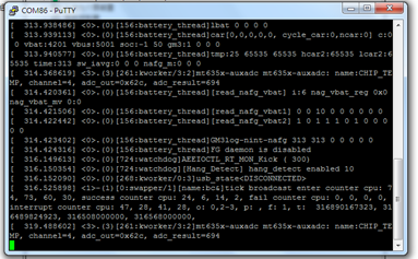
View of debug log messages appearing from UART0 upon board bootup
Verify the desktop screen appears as shown above in the image Genio 350-EVK Demo System Image
EVK Basic Testing
Objective
To verify the flashed image boots up successfully and board’s ability to connect to WiFi, access a web browser, and play audio-visual content.
Steps
Boot the Board: - Ensure the board is fully powered on and has completed the booting process.
Connect to WiFi: - Navigate to the ‘Settings’ menu on the board. - Locate the ‘WiFi’ option and select it. - Choose the desired WiFi network from the list of available networks. - Enter the necessary credentials (e.g., password) to connect to the WiFi network. - Confirm that the board is successfully connected to the WiFi network.
Open the Browser: - Launch the web browser application on the board. - In the browser’s address bar, type the URL:
www.youtube.com. - Press ‘Enter’ or select the ‘Go’ button to navigate to the YouTube website.Play Audio-Visual Content: - On the YouTube homepage, search for or select any video content. - Click on the video to start playback. - Confirm that the audio and video are playing correctly without interruptions or errors.
Note
Ensure that the WiFi network is operational and accessible.
Note
HDMI: Connect an HDMI cable from the board to your TV/monitor with speakers.
Audio Jack: Connect a 3.5mm cable from the board to speakers/headphones.
Ensure your audio device is powered on and set to the correct input.