i350 EVK Board
The EVK is a development board made by MediaTek.
Building
You can build an image for the Innocomm SB35 board by setting the MACHINE variable in your local.conf to i350-evk.
MACHINE=i350-evk
For full build instructions, please refer to the top level README.md.
DSI Display
The i350 EVK supports the Startek KD070FHFID015 DSI display.
If you wish to use the DSI display, the related overlay is recipes-kernel/dtbo/mt8365-evk/panel-startek-kd070fhfid015.dts
Warning
Using panel-startek-kd070fhfid015.dts requires you to plug the DSI display to your board. Failing to connect it will prevent HDMI from working. If you only want HDMI, you should not use this overlay.
Ethernet and HDMI support
Ethernet and HDMI are sharing the same pins, which means only one is available at a time.
Ethernet
To use Ethernet, make sure you select the LAN feature on the SW2101 switch. In addition because Ethernet is disabled by default in the kernel device-tree, you will also need to load an overlay to enable Ethernet.
If you wish to use Ethernet, the related overlay is recipes-kernel/dtbo/mt8365-evk/net-ethernet.dts
HDMI
To use HDMI, make sure you select the DPI feature on the SW2101 switch. By default HDMI is enabled in the kernel device-tree. Make sure the Ethernet overlay is not loaded otherwise HDMI would get disabled (see Ethernet section).
MT7663 wireless chipset
The i350 EVK board is integrating a MT7663 wireless chipset.
Device-Tree Overlays (DTBO)
The following Device-Tree Overlays are supported:
net-ethernet.dtbo: Enable support for Ethernet (see Ethernet section)
FTDI board control
The i350 EVK has two FTDI chips connected to the UART0 (CON461) port and to the UART1 (CON462) port. They are both able to control the power (PWRKEY), reset (SYSRST), and download (KPCOL0) lines.
FTDI GPIO Line |
Function |
|---|---|
0 |
Power (PWRKEY) |
1 |
Reset (SYSRST) |
2 |
Download (KPCOL0) |
Audio
Playback
By default, the i350 EVK board ouputs audio on the first jack connector (headset) and the second jack (line out) is disabled.
It is possible to switch to the second line. In order to do that, you will need to change several alsa settings using the following commands:
In order to disable the headset output and enable the Line out:
amixer sset -c mtsndcard 'Audio_Amp_L_Switch',0 Off
amixer sset -c mtsndcard 'Audio_Amp_R_Switch',0 Off
amixer sset -c mtsndcard 'Speaker_Amp_Switch',0 On
In order to switch back to Headset out:
amixer sset -c mtsndcard 'Audio_Amp_L_Switch',0 On
amixer sset -c mtsndcard 'Audio_Amp_R_Switch',0 On
amixer sset -c mtsndcard 'Speaker_Amp_Switch',0 Off
The following command is an example that will start a music playback of a wav file that is already on the device:
aplay playback_file.wav
Capture
By default, the i350 EVK board captures audio using the jack microphone.
The following command is an example that will start a mono record with a sampling rate of 48kHz and a signed 32bits bit format:
arecord -c 1 -r 48000 -f s32_le recorded_file.wav
It is possible to record using the 2 PDM mics present on the board instead. In this case, the device will need to be specified explicitally as follows:
arecord -D dmic -c 2 -r 48000 -f s32_le recorded_file.wav
Another possibility is using the Analog mic also present on the board. In that case, you will need to switch from the jack mic to the analog mic using the following command:
amixer sset -c mtsndcard 'Audio_MicSource1_Setting',0 ADC1
Then use a similar command as for jack mic:
arecord -c 1 -r 48000 -f s32_le recorded_file.wav
In order to switch back to jack mic, use the following command:
amixer sset -c mtsndcard 'Audio_MicSource1_Setting',0 ADC2
USB audio
USB audio is supported on this board. Simply plug an USB audio device (an USB headset for example) and check its id or name before playing or recording something.
In order to play a wav file:
# List the playback devices
aplay -l
# If USB card id is 1 and its playback device id is 0,
# using the following command (forcing the framerate
# to 48HHz)
aplay -D plughw:1,0 -r 48000 playback_file.wav
In order to record a wav file:
# List the capture devices
arecord -l
# If USB card id is 1 and its capture device id is 0,
# using the following command (forcing the framerate
# to 48HHz)
arecord -D plughw:1,0 -r 48000 -c 1 -f s32_le recorded_file.wav
Cameras
The i350_evk board supports the following csi camera configs:
Single Onsemi AP1302 ISP + AR0430 sensor on CSI0
Single Onsemi AP1302 ISP + AR0430 sensor on CSI1
Dual Onsemi AP1302 ISP + AR0430 sensor on CSI0 and CSI1
Based on the necessary config, you need to use the following dtbo:
camera-ap1302-ar0430-single-csi0.dtbo
camera-ap1302-ar0430-single-csi1.dtbo
camera-ap1302-ar0430-dual.dtbo
For example, if you are using CSI0 only, the related overlay is recipes-kernel/dtbo/mt8365-evk/camera-ap1302-ar0430-single-csi0.dts
When flashing the board:
aiot-flash -i rity-demo-image --load-dtbo camera-ap1302-ar0430-single-csi0.dtbo
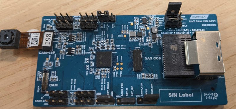
Hardware Setup
To have the correct hardware setup to work with the AP1302 ISP and AR0430 sensor, please check:
The position of the jumpers on J501, J502, J401, J402, J403 and J404 should be the same as shown in the image
The sensor should be connected on CN602 (CAM+ISP) as shown in the image
Media Setup
To configure the media pipeline and access the ISP + sensor, you can use the media-ctl application from the v4l-utils package.
media-ctl can be used to print the hardware components that are available to interconnect:
media-ctl -p -d0
You should be able to see the following entities:
mtk-mdp:m2m-source
mtk-mdp:m2m-proc
mtk-mdp:m2m-sink
By running:
media-ctl -p -d1
You should be able to see the following entities:
15040000.seninf
15050000.camsv
15050000.camsv video stream
ap1302.2-003d
ar0430
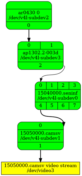
The interconnection of the components must ensure that the links between a source and a link pad have the same format (fmt). Also, the source from sensor AR0430 must have the format SGRBG12_1X12/2316x1746 and, on camsv, the final sink must be of UYVY8_1X16/2316x1746 format.
If those rules are not being respected, you can use the command:
media-ctl -d /dev/media1 -V "42:2 [fmt:UYVY8_1X16/2316x1746]"
to change the format of an entity:pad.
In addition, all the connexions between the components must be enabled. If there is any which is not, you can use the command:
media-ctl -d /dev/media1 -l "42:2->1:1[1]"
to enable the link between entity:pad_src and entity:pad_sink.
After this setup, the topology for one sensor on CSI0 must be similiar to the one shown in the image:
Listing Cameras
With the previous setup ok, you can use cam command, from libcamera, to list all the cameras connected to the board. If you run the command:
cam -l
the application should find a camera:
Available cameras:
1: Internal front camera (/base/soc/i2c@11009000/camera@3d)
Previous result was an example with one sensor and one ISP at CSI0.
Frames Capture
With the media setup ok, you should also be able to capture some image frames.
v4l2-ctl --set-fmt-video=width=2316,height=1746,pixelformat=UYVY --stream-mmap=1 --stream-count=10 --stream-to=v4l2_out -d /dev/video3 --verbose
Using the command above, a file named v4l2_out should have been created containing 10 frames 2316x1746 with format UYVY. You can then use another tool, such as ffmpeg, to be able to verify the frames.
ffmpeg -f rawvideo -s 2316x1746 -pix_fmt uyvy422 -i v4l2_out image"%03d.png